Unlock instant, AI-driven research and patent intelligence for your innovation.
Pressure dewatering machine for sludge
What is Al technical title?
Al technical title is built by PatSnap Al team. It summarizes the technical point description of the patent document.
A dehydrator and sludge technology, applied in dehydration/drying/concentrated sludge treatment, filtration separation, fixed filter element filter, etc., can solve the problems of low dehydration rate and unsatisfactory dehydration effect, and achieve simple overall structure , significant filtering effect and easy operation
Active Publication Date: 2012-05-30
鲍则宇
View PDF0 Cites 2 Cited by
Summary
Abstract
Description
Claims
Application Information
AI Technical Summary
This helps you quickly interpret patents by identifying the three key elements:
Problems solved by technology
Method used
Benefits of technology
Problems solved by technology
[0004] The purpose of the present invention is to overcome the problems of low dehydration rate and unsatisfactory dehydration effect of existing sludge dewatering machines, and provide a sludge pressure that can dehydrate sludge solution with high water content to dry sludge with low water content. dehydrator
Method used
Image
Click on the blue label to locate the original text in one second.
Reading with bidirectional positioning of images and text.
Examples
Embodiment 1
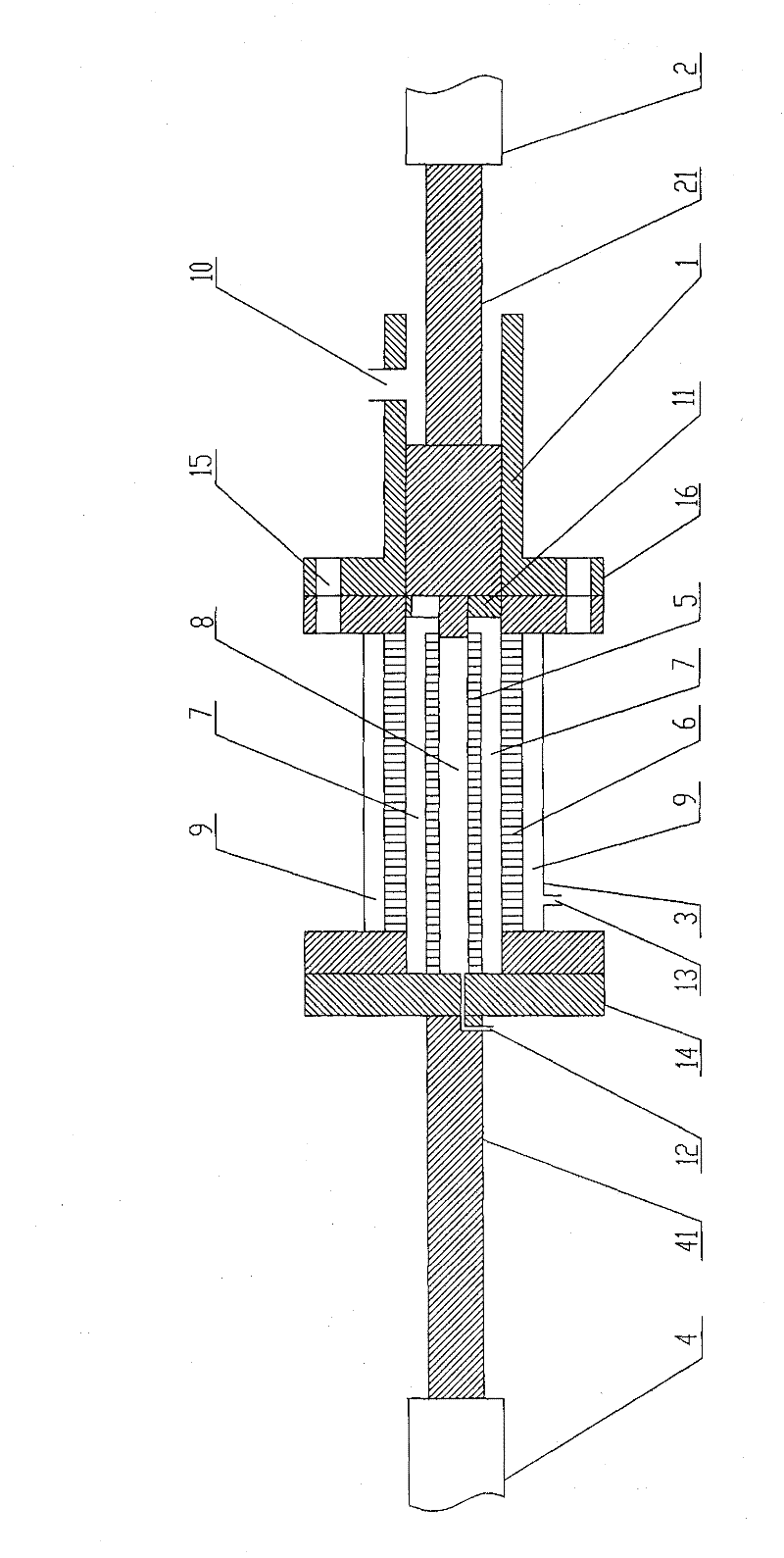
[0025] Such as Figure 1 ~ Figure 4 , Figure 6 , Figure 7 As shown, a sludge pressure dewatering machine includes the main components as follows:
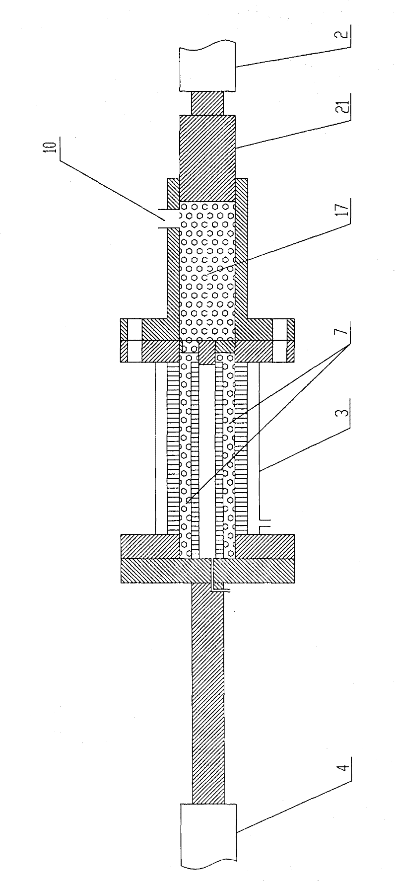
[0027] A sludge pressure dehydrator, comprising a cylinder body 1 and a feed piston 21 arranged in the sludge cavity 17 inside the cylinder body 1, the end of the feed piston 21 is provided with a feed oil cylinder 2, and the feed oil cylinder 2 feeds The feed force of the feed piston 21 allows the feed piston 21 to move back and forth in the sludge cavity 17 in the cylinder body 1 .
[0028] The cylinder body 1 is connected with the filter chamber body 3 , and the cylinder body 1 and the filter chamber body 3 are provided with bolt holes 15 at corresponding positions, and are sealed and connected through the bolt holes 15 . A flange 16 is also provided ...
Embodiment 2
[0035] Such as Figure 1 to Figure 7 As shown, a sludge pressure dewatering machine includes the main components as follows:
[0037] The connection relationship of the above components is:
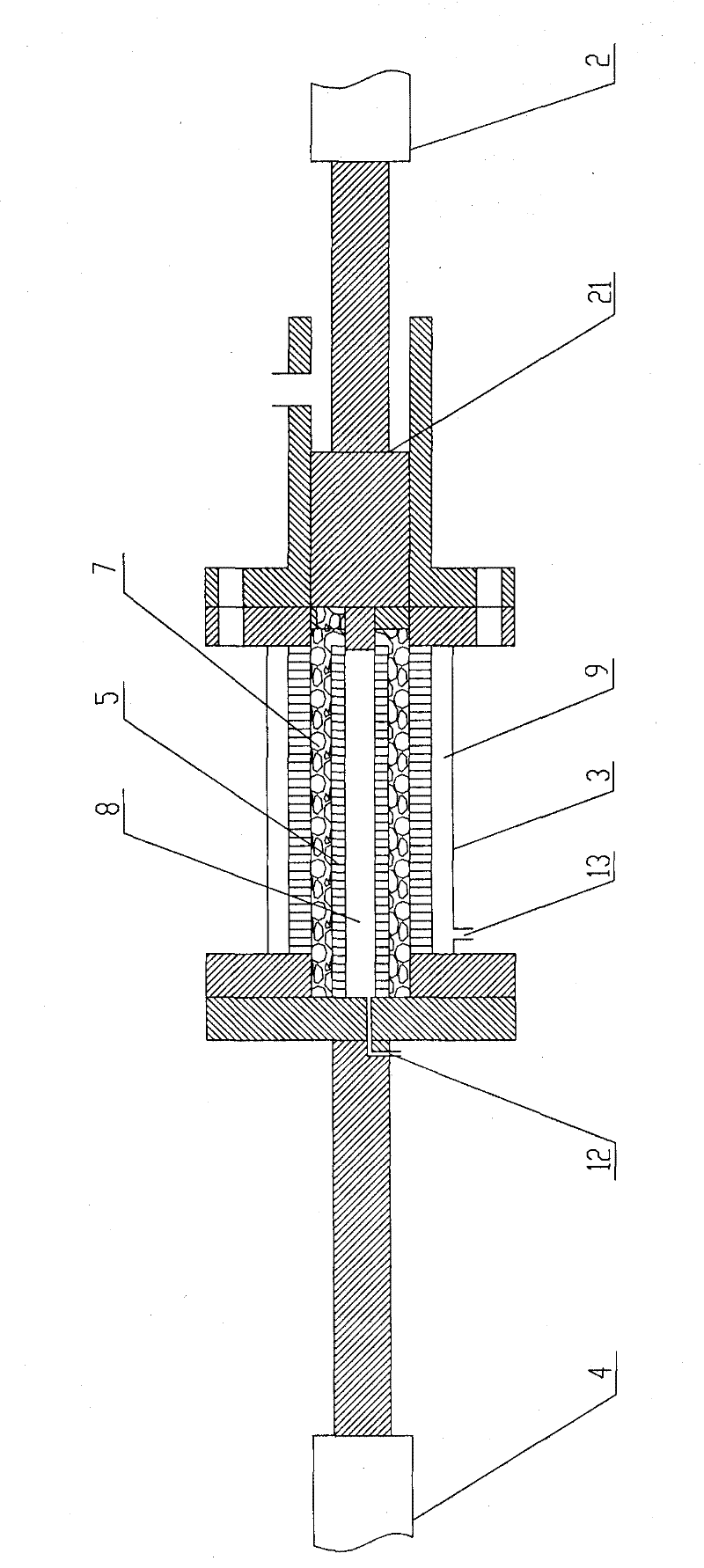
[0038] A sludge pressure dehydrator, comprising a cylinder body 1 and a feed piston 21 arranged in the sludge cavity 17 inside the cylinder body 1, the end of the feed piston 21 is provided with a feed oil cylinder 2, and the feed oil cylinder 2 feeds The feed force of the feed piston 21 allows the feed piston 21 to move back and forth in the sludge cavity 17 in the cylinder body 1 .
[0039]The cylinder body 1 is connected with the filter chamber body 3 , and the cylinder body 1 and the filter chamber body 3 are provided with bolt holes 15 at corresponding positions, and are sealed and con...
PUM
Abstract
The invention discloses a pressure dewatering machine for sludge, which comprises a cylinder body and a feeding piston arranged in a sludge cavity inside the cylinder body, wherein the end part of the feeding piston is provided with a feeding cylinder; the cylinder body is connected with a filtration chamber; the sludge cavity of the cylinder body is communicated with the inner cavity of the filtration chamber; the cylinder body is provided with a sludge feeding port communicated with the sludge cavity inside the cylinder body; outer filters are arranged in the inner cavity of the filtration chamber, and are combined and connected into a hollow filtration cavity by a plurality of outer filter discs; the filtration cavity is communicated with the sludge cavity of the cylinder body; an outer water collection chamber is formed between the outer filters and the wall of the filtration chamber; the side wall of the filtration chamber is provided with a water outlet hole A communicated with the outer water collection chamber; an unloading piston is movably and tightly connected at one end symmetrical with the connection end of the filtration chamber and the cylinder body by a sealing endcover; and the unloading piston is connected with an unloading cylinder. By using the inner and outer filters to carry out bidirectional high-pressure extrusion on the moisture in the sludge, the invention improves the sludge dewatering efficiency.
Description
technical field [0001] The invention relates to a sludge dewatering device, in particular to a sludge pressure dehydrator. Background technique [0002] At present, my country's sewage treatment enterprises produce a large amount of sludge with high water content in the process of sewage treatment. There are a large amount of perishable organic matter, bacteria, viruses and heavy metals in the sludge. These sludge must be dehydrated for subsequent treatment and disposal. . However, the sludge dewatering equipment currently used by sewage treatment enterprises in my country: drum centrifuge, belt dehydrator and plate and frame filter press, due to structural limitations, it is difficult to increase the pressure and centrifugal force of the equipment, and the moisture content of the sludge after dehydration is 75%. -85%, regardless of subsequent disposal methods such as landfill, composting and incineration, the cost of disposal is very high. Therefore, how to further reduce t...
Claims
Application Information
Patent Timeline
Application Date:The date an application was filed.
Publication Date:The date a patent or application was officially published.
First Publication Date:The earliest publication date of a patent with the same application number.
Issue Date:Publication date of the patent grant document.
PCT Entry Date:The Entry date of PCT National Phase.
Estimated Expiry Date:The statutory expiry date of a patent right according to the Patent Law, and it is the longest term of protection that the patent right can achieve without the termination of the patent right due to other reasons(Term extension factor has been taken into account ).
Invalid Date:Actual expiry date is based on effective date or publication date of legal transaction data of invalid patent.
