Stirring type flotation machine for recycling tailings

A stirring type, flotation machine technology, applied in the field of flotation machines, can solve the problems of difficult dispersion of bubbles, low flotation efficiency, limited ore quantity, etc., and achieve the effect of helping dispersion and avoiding directional ejection

Pending Publication Date: 2022-07-01
刘世力
View PDF0 Cites 0 Cited by
  • Summary
  • Abstract
  • Description
  • Claims
  • Application Information

AI Technical Summary

Problems solved by technology

[0003] The existing agitated flotation machines are generally screened by chemicals and agitation when stirring the ore pulp, and by filling the flotation machine with gas, the gas forms foam, wraps the small particles of ore, and gradually floats, Then, through the rotating scraper, the small particles of ore that floated out of the water are taken out. After the existing flotation machine is passed in, the bubbles formed are difficult to disperse, resulting in a limited number of ore floated, which in turn leads to low flotation efficiency. , so a corresponding improvement is made for this problem

Method used


Image

  • Stirring type flotation machine for recycling tailings
  • Stirring type flotation machine for recycling tailings
  • Stirring type flotation machine for recycling tailings

Examples


Embodiment 1

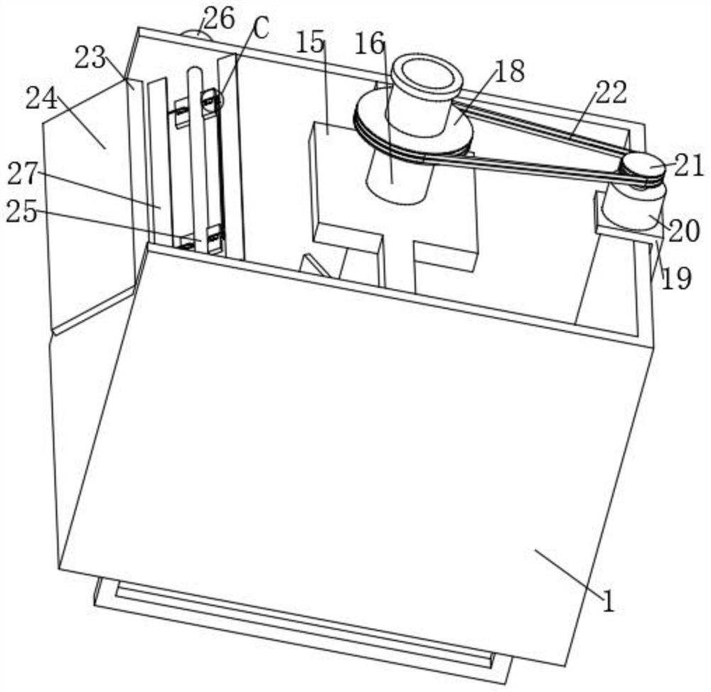
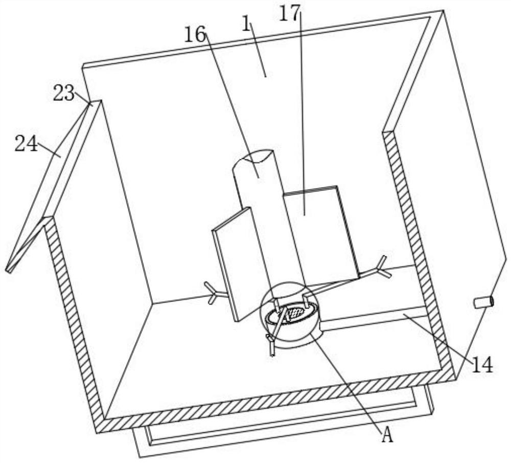
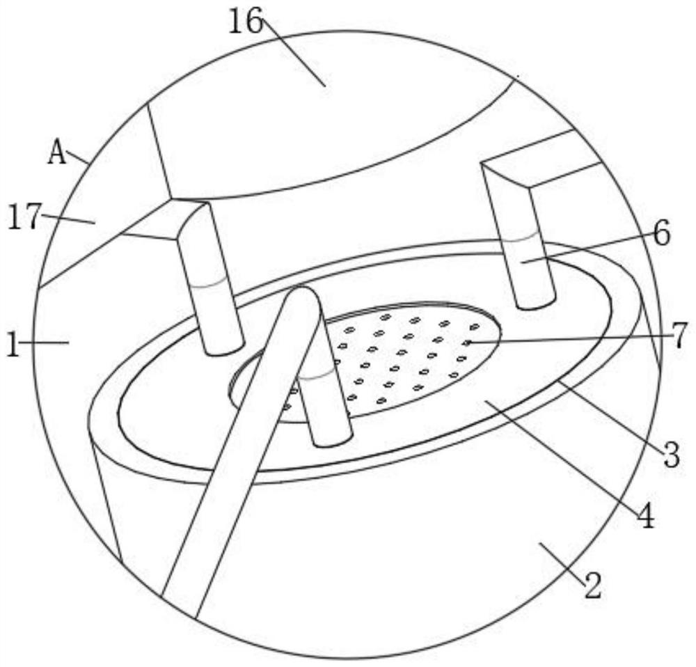
[0030] refer to Figure 1-8 , a tailings recovery stirring flotation machine, including a box 1, the bottom of the box 1 is fixed with a gas accumulator 2 through bolts, one side of the gas accumulator 2 is connected with an air intake pipe 14, and the other side of the air intake pipe 14 penetrates the box body 1. An installation port 3 is provided on the top of the gas accumulator 2, and a disc 4 is rotatably connected in the installation port 3 through a bearing. The top of the disc 4 is provided with a plurality of exhaust ports 5 distributed in an annular array. The top of the exhaust port 5 is connected with The exhaust pipe 6, the exhaust pipe 6 is L-shaped as a whole, and the head of the exhaust pipe 6 is Y-shaped, the bottom of the disc 4 is fixed with a connecting column 8 by bolts, and the bottom of the connecting column 8 is welded and fixed with a mounting plate 9. A plurality of blades 10 distributed in an annular array are fixed on the circumferential outer wall...

Embodiment 2

[0041] refer to Figure 1-9 , a tailings recovery stirring flotation machine, a box 1, the bottom of the box 1 is fixed with a gas accumulator 2 by bolts, one side of the gas accumulator 2 is connected with an air intake pipe 14, and the other side of the air intake pipe 14 penetrates the box body 1 , the top of the gas accumulator 2 is provided with an installation port 3, and a disc 4 is connected in the installation port 3 through the bearing rotation. The air pipe 6 and the exhaust pipe 6 are L-shaped as a whole, and the head of the exhaust pipe 6 is Y-shaped. The bottom of the disc 4 is fixed with a connecting column 8 by bolts, and the bottom of the connecting column 8 is welded and fixed with a mounting plate 9. The mounting plate 9. A plurality of blades 10 distributed in an annular array are fixed on the outer wall of the circumference by bolts, and a stirring mechanism and a scraping mechanism are arranged in the box body 1.

[0042] Further, a densely clothed first...


PUM


Abstract

The invention belongs to the technical field of flotation machines, and particularly relates to a tailing recovery stirring type flotation machine which comprises a box body, an air gathering cylinder is fixed in the bottom of the box body through bolts, one side of the air gathering cylinder communicates with an air inlet pipe, the other side of the air inlet pipe penetrates through the box body, and a mounting opening is formed in the top of the air gathering cylinder; a plurality of exhaust ports distributed in an annular array are formed in the top of the disc in a penetrating mode, the tops of the exhaust ports communicate with exhaust pipes, the exhaust pipes are integrally in an L shape, the pipe heads of the exhaust pipes are in a Y shape, connecting columns are fixed to the bottom of the disc through bolts, and a mounting disc is fixedly welded to the bottoms of the connecting columns. A plurality of blades distributed in an annular array mode are fixed to the outer wall of the circumference of the mounting disc through bolts, and a stirring mechanism and a scraping mechanism are arranged in the box body. According to the device, airflow acts on the blades, so that the exhaust pipe rotates, bubbles are formed in the rotating process, and the bubbles are uniformly dispersed.

Description

technical field [0001] The invention relates to the technical field of flotation machines, in particular to a tailings recovery stirring flotation machine. Background technique [0002] Flotation machine is the abbreviation of flotation concentrator, which refers to the mechanical equipment that completes the flotation process. In the flotation machine, the ore pulp treated with chemicals is stirred and aerated, so that some of the ore particles are selectively fixed on the air bubbles; they float to the surface of the ore pulp and are scraped out to form foam products, and the rest remain in the ore pulp In order to achieve the purpose of separating minerals, there are many structural forms of flotation machines, and the most commonly used is the mechanical stirring flotation machine. [0003] In the existing stirring flotation machine, the ore pulp is generally screened by chemicals and stirring, and by filling the flotation machine with gas, the gas forms foam, wraps the...

Claims


Application Information

Patent Timeline
Patent Type & Authority Applications(China)
IPC IPC(8): B03D1/16
CPCB03D1/16
Inventor 刘世力
Owner 刘世力
Why Eureka
Try Eureka