Fan blade structure and centrifugal fan with same

A centrifugal fan and fan blade technology, which is applied to components, instruments, and electrical digital data processing of elastic fluid pumping devices, etc. It can solve the problems of burning electronic components, reducing the operation speed of electronic components, and affecting the performance of electronic components. , to achieve the effect of large sweeping area and enhanced heat dissipation performance

Inactive Publication Date: 2011-07-20
FU ZHUN PRECISION IND SHENZHEN +1
View PDF6 Cites 17 Cited by
  • Summary
  • Abstract
  • Description
  • Claims
  • Application Information

AI Technical Summary

Problems solved by technology

[0002] In recent years, with the development of the electronics industry, the performance of electronic components has been continuously improved, and the calculation speed has become faster and faster. The calculation speed of the internal chipset has been continuously improved, the number of chips has continued to increase, and the heat emitted by the chips has also increased accordingly. If If the heat is not dissipated in time, the performance of electronic components will be greatly affected, and the computing speed of electronic components will be reduced. As the heat continues to accumulate, electronic components may be burned, so it is necessary to dissipate heat from electronic components

Method used


Image

  • Fan blade structure and centrifugal fan with same
  • Fan blade structure and centrifugal fan with same
  • Fan blade structure and centrifugal fan with same

Examples


Embodiment Construction

[0013] The present invention will be further described below in conjunction with the embodiments with reference to the accompanying drawings.

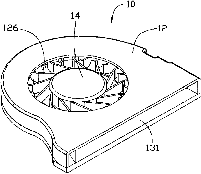
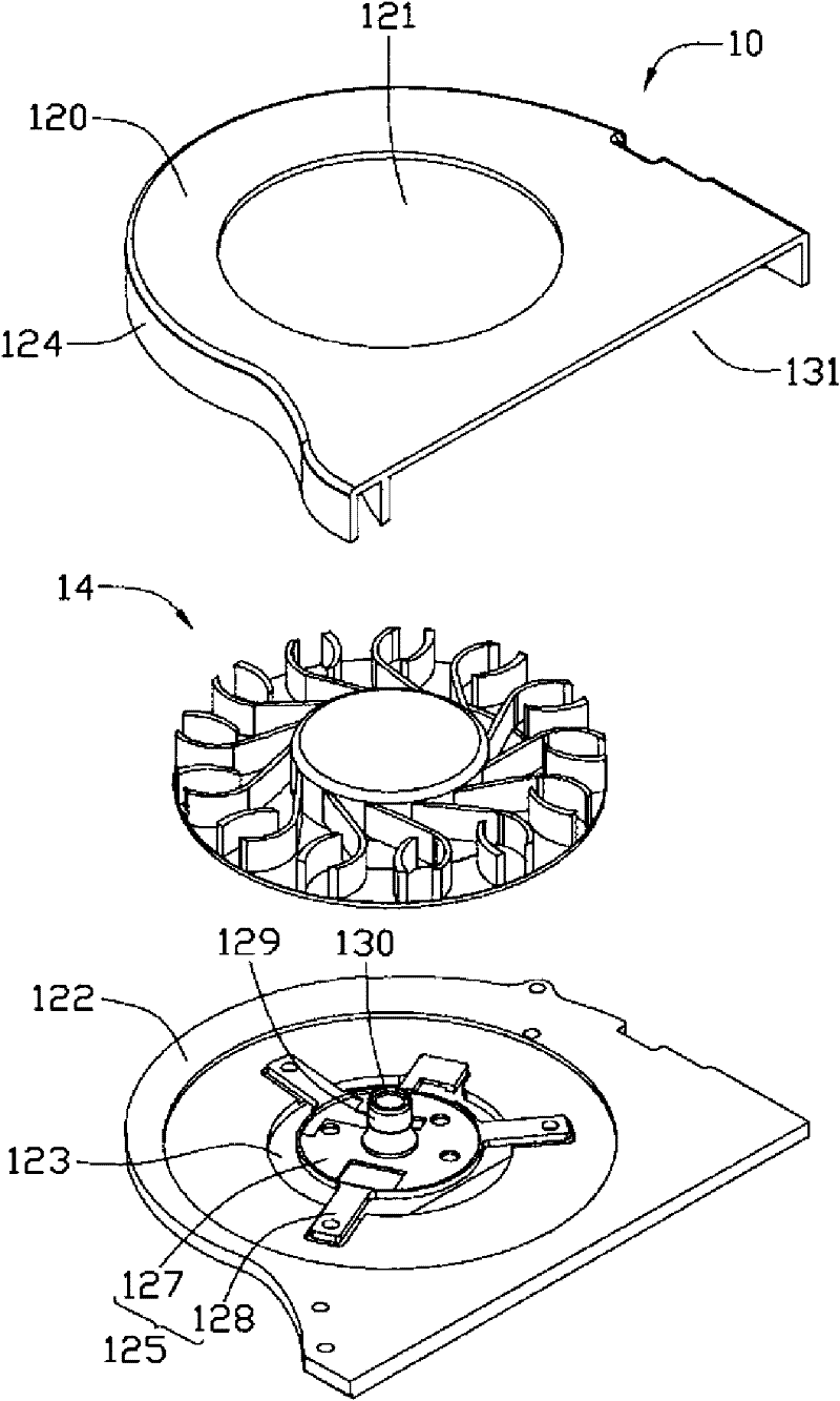
[0014] Such as figure 1 and figure 2 As shown, the centrifugal fan 10 includes a fan frame 12 and a fan blade structure 14 disposed in the fan frame 12 .

[0015] The fan frame 12 includes a top plate 120, a bottom plate 122 and a scroll-shaped side plate 124 connected between the top plate 120 and the bottom plate 122 and integrally formed with the top plate 120. The top plate 120, the bottom plate 122 and the side plate 124 share An accommodating space 126 for accommodating the blade structure 14 is formed. The top plate 120 and the bottom plate 122 are separately arranged on the upper and lower sides of the fan blade structure 14, and the central positions of the top plate 120 and the bottom plate 122, that is, the position of the fan blade structure 14 respectively form a circular upper and lower opening. The air outlets 121 , ...


PUM


Abstract

The invention relates to a fan blade structure and a centrifugal fan with the same. The fan blade structure comprises a hub and a plurality of first blades extending outwards along the outer edge of the hub, a blade disc which is arranged at ends of the first blades and is mutually connected with the first blades and a plurality of second blades which are arranged on the blade disc and are positioned among the first blades, wherein the ends of the first blades bend and extends outwards to form an arc-shaped part; the second blades are in an arc shape of which the direction is opposite to the bending direction of the arc-shaped part of each first blade; and the speed of air flow can be increased to allow more air flow on the inner side of the arc-shaped parts of the first blades to flow towards the outer periphery and fan frames of the fan blade structure, so that more air flow is discharged from an air outlet of the centrifugal fan to enhance the heat dispersion performance of the centrifugal fan.

Description

technical field [0001] The invention relates to a fan blade structure, in particular to a fan blade structure for a centrifugal fan. Background technique [0002] In recent years, with the development of the electronics industry, the performance of electronic components has been continuously improved, and the calculation speed has become faster and faster. The calculation speed of the internal chipset has been continuously improved, the number of chips has continued to increase, and the heat emitted by the chips has also increased accordingly. If If the heat is not dissipated in time, the performance of the electronic components will be greatly affected, and the computing speed of the electronic components will be reduced. As the heat continues to accumulate, the electronic components may be burned, so the electronic components must be dissipated. [0003] In electronic equipment with limited installation space such as notebook computers, a centrifugal fan is usually install...

Claims


Application Information

Patent Timeline
Patent Type & Authority Applications(China)
IPC IPC(8): F04D29/28F04D29/30
CPCF04D29/30F04D29/663G06F1/203F04D25/0613F04D29/281
Inventor 梁恩铭余方祥洪健隆
Owner FU ZHUN PRECISION IND SHENZHEN
Why Eureka
Try Eureka