Electromagnet and friction composite disc type brake and brake method

A technology of electromagnetic braking and composite disc, applied in the direction of brake type, axial brake, brake components, etc., can solve the problems affecting the thermal decay of the brake, the temperature rise of the brake disc, the temperature rise of the brake, etc., to achieve the braking force. The size is easy to control, the action time is reduced, and the effect of reducing the intensity of use

Inactive Publication Date: 2011-07-20
JIANGSU UNIV
View PDF8 Cites 40 Cited by
  • Summary
  • Abstract
  • Description
  • Claims
  • Application Information

AI Technical Summary

Problems solved by technology

During the high-speed driving of the car, during emergency braking, the action time of the brake and the braking force have a great influence on the braking performance, and the action time of the hydraulic oil circuit of the disc brake and the movement time of the brake block will reduce the braking efficiency , and a lot of noise will be generated during the braking process, and the temperature of the brake disc will rise, which will affect the thermal degradation of the brake, thereby affecting the braking performance
Especially in the continuous braking process such as long downhill, or in the case of frequent braking, the temperature of the brake rises sharply, and the friction of the brake block is severe, resulting in serious wear

Method used


Image

  • Electromagnet and friction composite disc type brake and brake method
  • Electromagnet and friction composite disc type brake and brake method
  • Electromagnet and friction composite disc type brake and brake method

Examples


Embodiment Construction

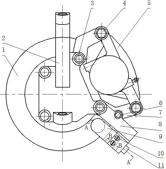
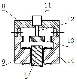
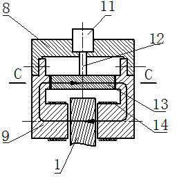
[0016] see figure 1 , 6 , 7, the present invention adds another brake caliper body 5 at one end of the brake caliper body of the traditional disc brake, the brake caliper body 5 is connected with the brake caliper bracket 7 through the brake caliper guide pin 4, and the brake caliper bracket 7 Located beside the brake disc 1, a steering knuckle 2 is arranged beside the brake disc 1, and a through hole is opened on the brake caliper support 7, and the brake caliper support 7 is connected to the steering knuckle 2 through bolts 3. The specific shape and size of the electromagnetic brake fixing device 8 are determined according to the size of the designed magnetic brake. One section of the electromagnetic brake fixing device 8 is also fixedly connected to the steering knuckle 2 through a bolt 3, and the other section is fixedly connected to the steering knuckle 2 through another bolt 6. Moving clamp bracket 7.

[0017] see Figure 1-5 , The electromagnetic brake fixing device ...


PUM


Abstract

The invention provides an electromagnet and friction composite disc type brake and a brake method. Both a steering knuckle and a brake caliper bracket are fixedly connected with an electromagnet brake fixing device, and the electromagnet brake fixing device is fixedly connected with magnet cores. The magnet cores are symmetrically arranged on the two sides of a brake disc, and coil windings are wound on the magnet cores. Permanent magnet bodies and the magnet cores are oppositely arranged, and air gaps are arranged between the permanent magnet bodies and the magnet cores. When an automobile brakes, electromagnet fields distributed on the axes of the coil windings are generated after the coil windings are electrified, and the directions of the electromagnet fields generated by the coil windings on the two sides of the brake disc are consistent. The permanent magnet bodies rotate 90 DEG, the directions of the permanent magnet fields of the permanent magnet bodies are consistent with the directions of the electromagnet fields of the coil windings, and the brake disc is braked by the superposition of the electromagnet fields and the permanent magnet fields. The size of the brake force is adjusted by adjusting the different rotating angles of the permanent magnet bodies or the size of electrifying current in the coil windings. The action time of the brake is shortened, the brake efficiency is enhanced, the use strength of the friction brake is reduced, the abrasion of brake pads is alleviated, and the brake force is easy to control.

Description

technical field [0001] The invention relates to an automobile brake, which can brake or decelerate the automobile. Background technique [0002] At present, the commonly used automobile brakes are mostly disc brakes. The disc brake uses hydraulic oil to drive the piston in the brake caliper. The piston presses the brake block to the brake disc, and the disc and brake block The friction between them slows down the speed of the vehicle. During the high-speed driving of the car, during emergency braking, the action time of the brake and the braking force have a great influence on the braking performance, and the action time of the hydraulic oil circuit of the disc brake and the movement time of the brake block will reduce the braking efficiency , and a lot of noise will be generated during the braking process, and the temperature of the brake disc will rise, which will affect the thermal degradation of the brake, thereby affecting the braking performance. Especially in the co...

Claims


Application Information

Patent Timeline
Patent Type & Authority Applications(China)
IPC IPC(8): F16D65/21F16D65/18F16D55/00
Inventor 何仁张端军
Owner JIANGSU UNIV
Why Eureka
Try Eureka