Cold and hot exchange device

A technology of cold and heat exchange and water cooling, which is applied in the direction of refrigerators, indirect heat exchangers, refrigeration and liquefaction, etc. It can solve the problem that heating and cooling appliances cannot reach the temperature when exhausting cold or heat, and the temperature of cold chips cannot be lowered or taken away quickly, etc. Problems, to achieve fast heat transfer, environmental protection and economy, and increase the effect of practicability

Inactive Publication Date: 2011-07-20
林义民
View PDF1 Cites 9 Cited by
  • Summary
  • Abstract
  • Description
  • Claims
  • Application Information

AI Technical Summary

Problems solved by technology

[0003] Traditional air conditioners need to use refrigerants. However, the manufacture and recycling of refrigerants will cause serious environmental pollution problems. For this reason, many people in the industry have actively developed air conditioners that can replace refrigerants. For example, the first application in Taiwan, China Patent No. I284188, which discloses a cooling and heating appliance using semiconductors. The heating and cooling appliance is made using the principle of a thermoelectric cooling chip (Thermoelectric Cooling Chip) and a cold circulator. It mainly includes a thermoelectric cooling chip, a cold circulator, and a heat dissipation cycle device. And the thermostat, the cold air is generated by the thermoelectric cooling chip, and then passed through the cold guide plate through the cold circulator to the fins to store the cold air, and then the temperature controller is used to set the required temperature, and the cold air stored in the fins is passed through the fan Blowing, and the heat energy generated by the cooling chip is cooled and removed by the heat dissipation circulation equipment, so as to achieve the set coldness
[0004] The above-mentioned patent uses a thermoelectric cooling chip to replace the cooling effect achieved by a traditional air conditioner using a compressor and a condenser. However, the reason why it cannot be commercialized is that its heat dissipation cycle cannot quickly take away a large amount of heat energy of the thermoelectric cooling chip. , so that the temperature of the thermoelectric cooling chip cannot be lowered to the required temperature, so that the cooling or heat removal of the heating and cooling appliance cannot reach the required temperature

Method used


Image

  • Cold and hot exchange device
  • Cold and hot exchange device
  • Cold and hot exchange device

Examples


Embodiment Construction

[0032] The detailed description and technical content of the present invention are described below with accompanying drawings. However, the attached drawings are provided for reference and illustration only, and are not intended to limit the present invention.

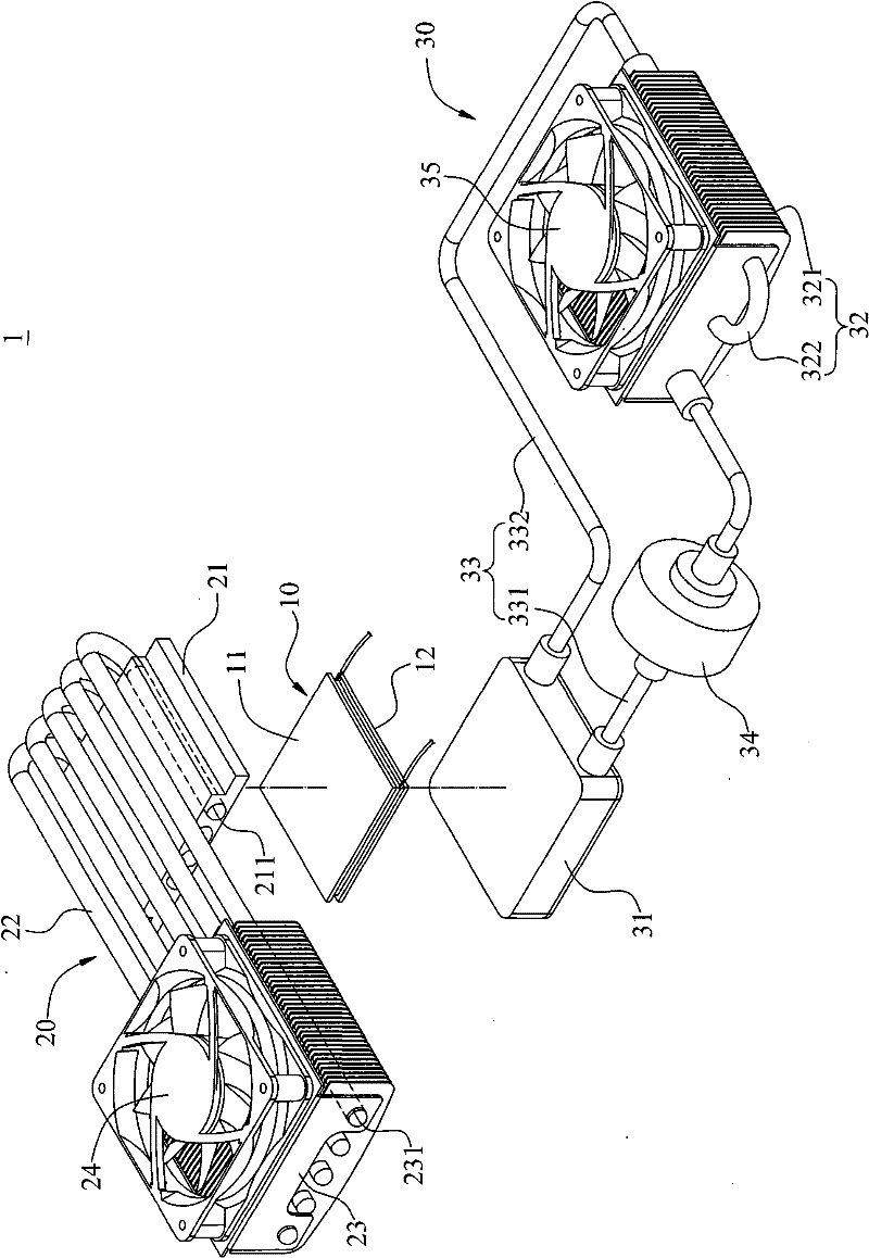
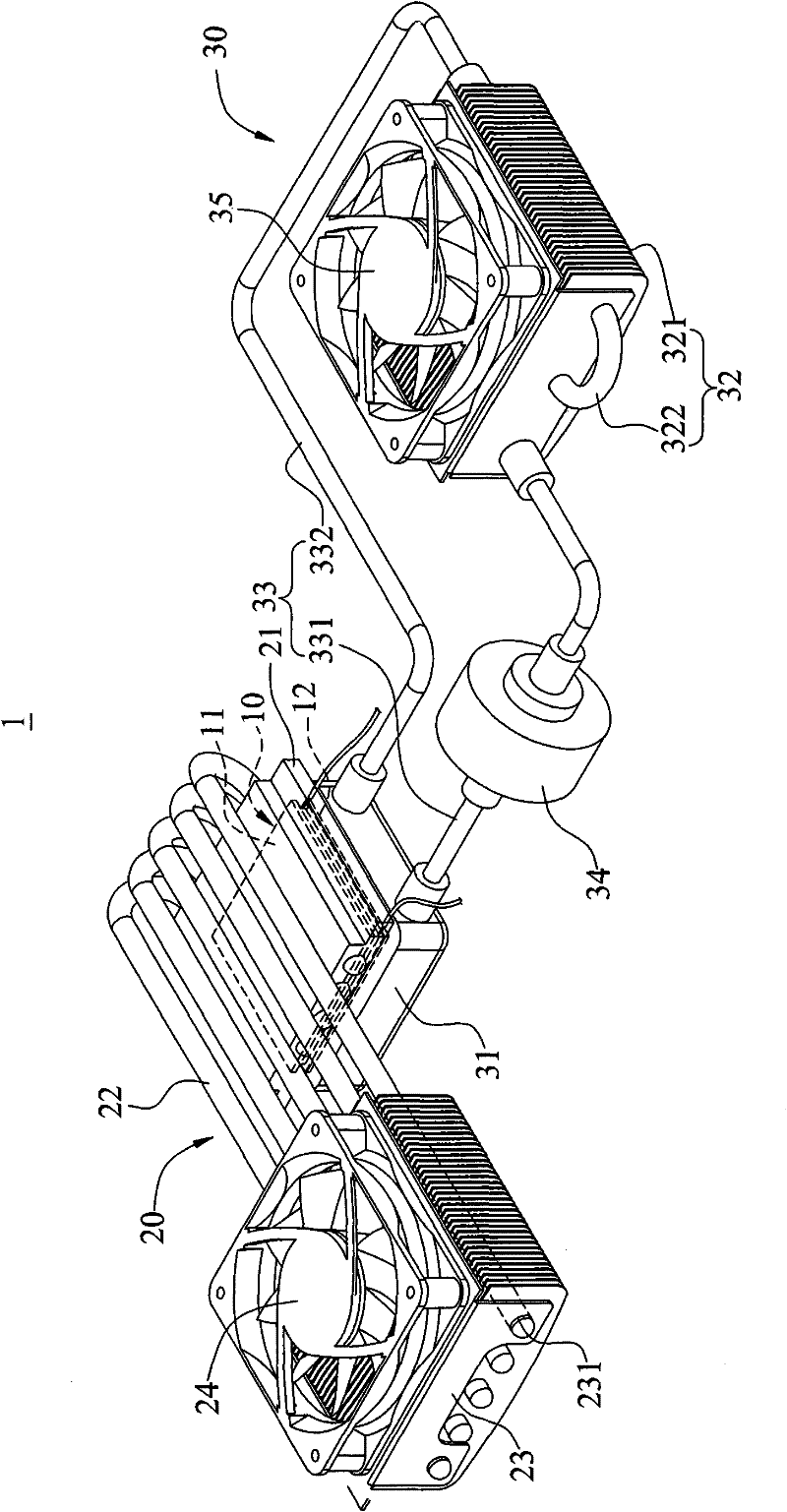
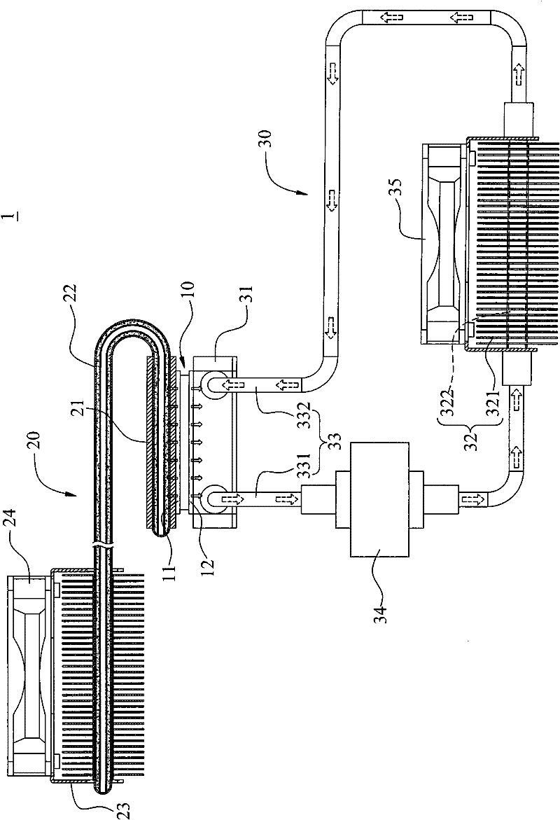
[0033] Please refer to Figure 1 to Figure 3 , are respectively an exploded schematic diagram, a three-dimensional schematic diagram and a combined cross-sectional schematic diagram of the cold and heat exchange device of the present invention; the cold and heat exchange device 1 of the present invention includes a thermoelectric cooling chip (Thermoelectric Cooling Chip) 10, a first conduction module 20 and a second conduction module 30.

[0034] The thermoelectric cooling chip (hereinafter referred to as the cooling chip) 10 is made of thermoelectric conversion material. After the current is supplied to operate, the temperature of one end surface will rise to form a hot end surface 11, and the temperature of the othe...


PUM


Abstract

The invention discloses a cold and hot exchange device, which comprises a refrigerating chip with a hot end face and a cold end face which are opposite, a first conduction module and a second conduction module, wherein the first conduction module comprises a pedestal, two or more superconducting pipes and two or more first fins; the pedestal is jointed to the hot end face of the refrigerating chip, the superconducting pipes are fixed on the pedestal, superconducting liquid is filled in the superconducting pipes, the superconducting liquid performs one-way energy transfer in a mode of molecular collision, and the first fins are sleeved on the superconducting pipes; and the second conduction module comprises a water-cooled seat jointed to the cold end face of the refrigerating chip, a water-cooled bar arranged on the side of the water-cooled seat, a connecting pipe for connecting the water-cooled seat and the water-cooled bar and a water pump arranged on the connecting pipe. When the cold and hot exchange device is applied, required refrigerating or heating effect can be achieved.

Description

technical field [0001] The invention relates to a cold and hot air conditioner and a refrigerator, in particular to a cold and hot air conditioner and a refrigerator with a cooling chip. Background technique [0002] Generally, a traditional air conditioner is equipped with components such as a compressor, a condenser, and an evaporator, and the condenser is filled with a refrigerant, which generates a high-temperature and high-pressure vapor refrigerant through the action of the compressor. After the vapor refrigerant passes through the condenser ( Exhaust heat) will be condensed into liquid refrigerant, the refrigerant after heat exhaust flows to the evaporator, and the refrigerant evaporates under the pressure drop, that is, absorbs the heat of the indoor space at the same time to produce a cooling effect (exhaust cooling), and then the refrigerant passes through the compressor The high-temperature and high-pressure steam refrigerant is formed, and finally returns to the ...

Claims


Application Information

Patent Timeline
Patent Type & Authority Applications(China)
IPC IPC(8): F25B21/02F25B21/04F28D15/02F28D15/04
CPCF28D15/0266F28D15/046
Inventor 林义民
Owner 林义民
Why Eureka
Try Eureka