
Toxic gas in-situ detection device for drainage pipeline detection equipment

A detection equipment, toxic gas technology, applied in the field of toxic gas in-situ detection device, can solve the problem of less pipeline toxic gas

Active Publication Date: 2011-07-20
TSINGHUA UNIV
View PDF6 Cites 0 Cited by
  • Summary
  • Abstract
  • Description
  • Claims
  • Application Information

AI Technical Summary

Problems solved by technology

But at present, there are few detection equipment for toxic gas inside the pipeline

Method used


Image

  • Toxic gas in-situ detection device for drainage pipeline detection equipment
  • Toxic gas in-situ detection device for drainage pipeline detection equipment
  • Toxic gas in-situ detection device for drainage pipeline detection equipment

Examples


Embodiment Construction

[0020] The present invention provides an in-situ detection device for toxic gas used in drainage pipeline detection equipment. The present invention will be further described in detail below in conjunction with the accompanying drawings and specific embodiments.

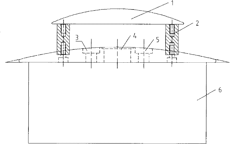
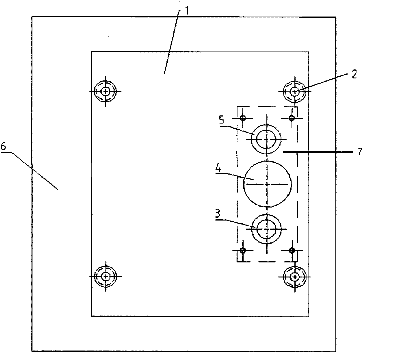
[0021] The gas detection device should be arranged above the box body of the pipeline video detection equipment to ensure that it will not touch the sewage in the pipeline. If the internal space of the detection equipment permits, the device can be directly arranged on the vehicle body (as in this embodiment) without making another device box to be carried on the vehicle body.

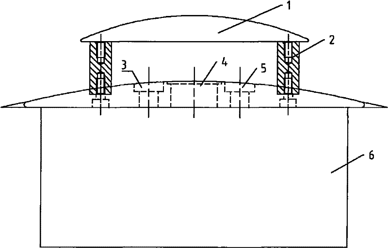
[0022] Such as figure 1 and figure 2 As shown, a water shield 1 supported by pillars 2 is provided on the top surface of the pipeline testing equipment box 6. The water shield 1 is a square convex arc plate, so that the water flow can flow away immediately without staying on its surface. The top and bottom of the pillar 2 are threaded hole...


PUM


Abstract

The invention relates to the technical field of gas detection, in particular to a toxic gas in-situ detection device for drainage pipeline detection equipment, wherein a waterproof cover supported by a strut is arranged on the top side of a box body of the pipeline detection equipment; a combustible gas sensor socket and a hydrogen sulfide sensor socket are arranged on the top side of the box body of the pipeline detection equipment and in the covering scope of the waterproof cover; the signals of a combustible gas sensor and a hydrogen sulfide sensor are output by two independent circuits and are controlled and displayed by control and display software; and the device can go deep into a drainage pipeline together with the pipeline detection equipment and can be used for in-situ detectingthe concentrations of the combustible gas and the hydrogen sulfide in the pipeline, thereby supplying a reference to pipeline entrance of workers, a part of non-excavation technical constructions, the deduction for waterpower condition and biochemical reaction in pipelines, and the like.

Description

technical field [0001] The invention relates to the technical field of gas detection, in particular to an in-situ detection device for toxic gas used for drainage pipeline detection equipment. Background technique [0002] During the operation of the drainage pipeline, if the sewage flow rate is slow, blocked, accumulated water or stagnant water occurs, the sewage cannot be discharged in time, which will easily lead to anaerobic reaction in the pipeline, producing toxic gases such as methane and hydrogen sulfide, thus causing workers Poisoning accidents caused by well inspection and workers working. [0003] Most of the existing gas detection methods use portable gas detectors to detect the concentration of toxic gases in the pipe at the wellhead or through a small suction pump. This method is limited by the effective measurement range of the instrument itself, and can only detect the local toxic gas concentration of the pipeline, and cannot understand the actual situation ...

Claims


Application Information

Patent Timeline
IPC IPC(8): G01N27/00
Inventor 左剑恶罗同顺干里里
Owner TSINGHUA UNIV
Learn More