

Wide-load range, high-precision and low-power consumption current detection circuit
A current detection circuit, high-precision technology, applied in the direction of measuring current/voltage, measuring devices, measuring electrical variables, etc., can solve the problems that the current detection circuit cannot guarantee the normal operation of a wide load range and the impact of detection accuracy
- Summary
- Abstract
- Description
- Claims
- Application Information
AI Technical Summary
Problems solved by technology
Method used
Image

Examples
Embodiment Construction
[0029] The following describes the implementation method of the technical solution of the invention in conjunction with the accompanying drawings:
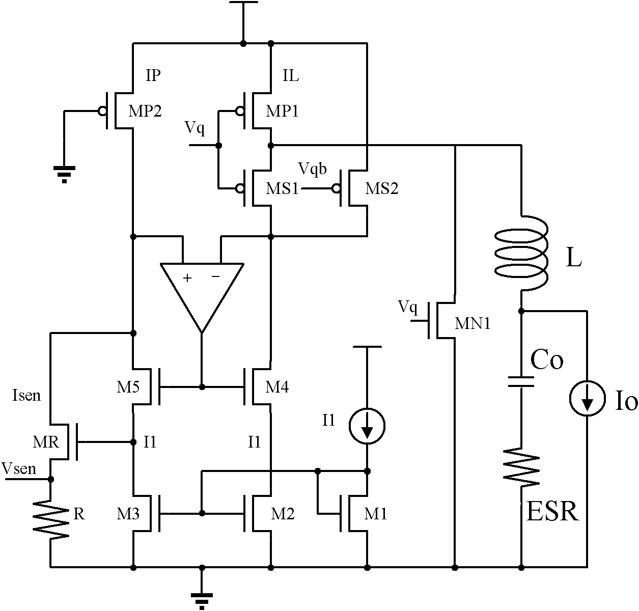
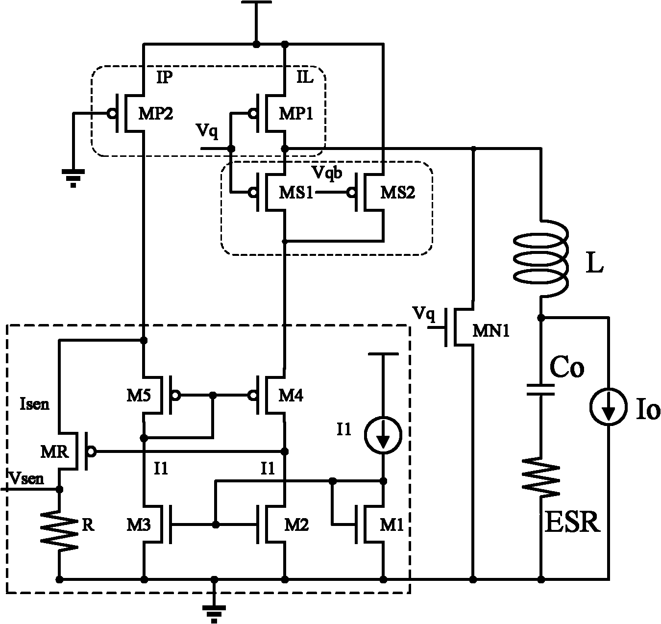
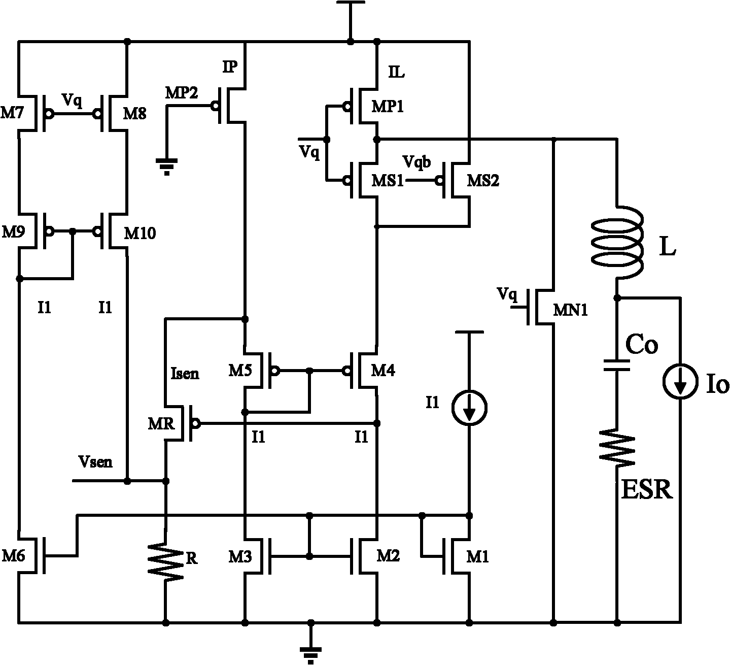
[0030] The traditional current detection circuit eventually needs to subtract the bias current I due to the induced current 1 The introduction of nonlinear errors reduces the detection accuracy, image 3 The current detection circuit invented in can eliminate non-linear errors. image 3 The circuit in the traditional current detection circuit figure 2 5 MOS tubes (M6-M10) are added to the base. M6 and M1-M3 together form a row of current mirrors, mirroring the currents in M1, M2, and M3. When the aspect ratio of M6 is equal to M1-M3, the current flowing through the 4 MOS transistors is equal. In this circuit, the current flowing through M6 is equal to the bias current I 1 . M9 and M10 have the same aspect ratio and are a pair of current mirrors, and the currents flowing through the two MOS tubes are also equal. M7 and M8 have the s...
PUM
 Abstract
Description
Claims
Application Information