Semiconductor packaging structure and making method thereof

A packaging structure and semiconductor technology, applied in the fields of semiconductor/solid-state device manufacturing, semiconductor devices, semiconductor/solid-state device components, etc., can solve the problems affecting the quality of electrical connections, densely interlaced bonding wires, and unfavorable wire bonding, etc. It is not easy to overflow and bridge, increase the quality of electrical connection, and has the effect of wide application range

Active Publication Date: 2013-01-16
SILICONWARE PRECISION IND CO LTD
View PDF2 Cites 0 Cited by
  • Summary
  • Abstract
  • Description
  • Claims
  • Application Information

AI Technical Summary

Problems solved by technology

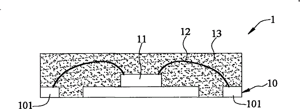
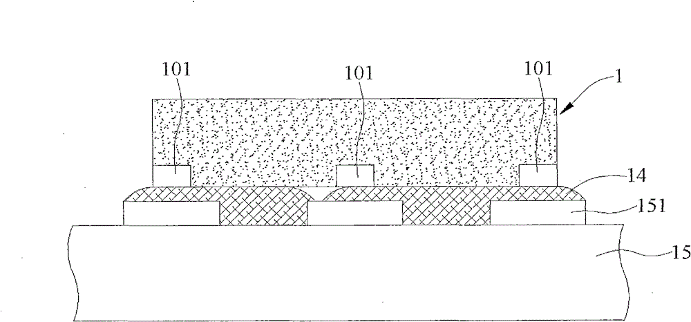
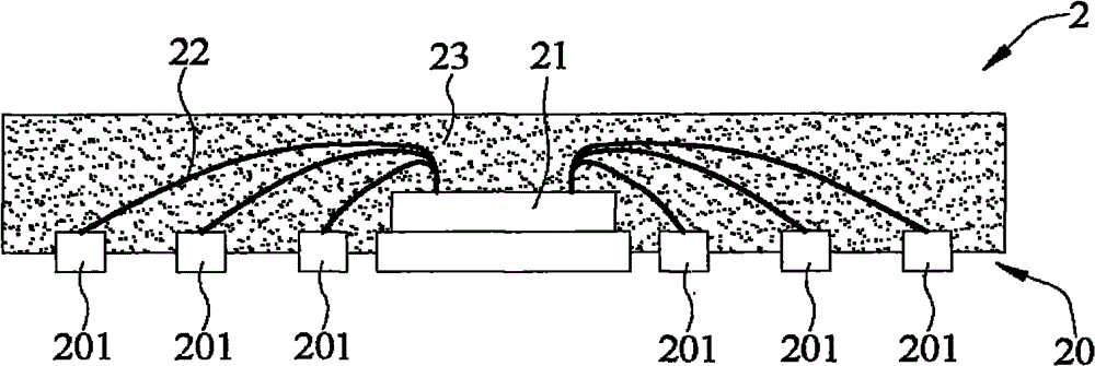
[0009] However, although the above-mentioned existing semiconductor package structure can provide a certain distance between the contact pads and the solder pads of the circuit board when soldering to the circuit board, and provide contact pads arranged in an array, the farther away from the semiconductor chip the contact pads are The longer the bonding wire is required, the bonding wire is too long to easily affect the quality of the electrical connection, and the bonding wires of the semiconductor package structure are densely intertwined, which is not conducive to the wire bonding, so it is still unable to provide higher density input / output (I / O )

Method used


Image

  • Semiconductor packaging structure and making method thereof
  • Semiconductor packaging structure and making method thereof
  • Semiconductor packaging structure and making method thereof

Examples


Embodiment Construction

[0060] Embodiments of the present invention are described below through specific examples, and those skilled in the art can easily understand other advantages and effects of the present invention from the contents disclosed in this specification.

[0061] see Figure 3A to Figure 3G , is a cross-sectional view of the semiconductor package structure and its manufacturing method of the present invention, wherein, Figure 3E' is a top view, Figure 3E is along Figure 3E' Cross-sectional view of line 3E-3E.

[0062] Such as Figure 3A As shown, the metal plate 30 is prepared, the metal plate 30 has an opposite first surface 30a and a second surface 30b, the first surface 30a has a crystal placement area 301 and a plurality of contact pad areas 302; wherein, the metal plate 30 The material can be copper.

[0063] Such as Figure 3B As shown, the metal plate 30 is patterned from the first surface 30a to the second surface 30b, so that the metal plate 30 forms grooves 300 in p...


PUM


Abstract

The invention relates to a semiconductor packaging structure comprising a dielectric layer, a metal layer, a plurality of metal posts, semiconductor chips and packaging colloid, wherein the metal is arranged on the dielectric layer and comprises a chip accommodating gasket and a plurality of path lines, each path line comprises a line body, a welded gasket extending to the periphery of the chip accommodating gasket and an opposite path line terminal; each metal post passes through the dielectric layer, one end of each metal post is connected with the chip accommodating gasket and the respective path line terminal, and the other end of the metal post protrudes out of the dielectric layer; the semiconductor chips are arranged on the chip accommodating gasket and electrically connected with the respective welded packets; and the packaging colloid is used for covering the semiconductor chips, welding wires, the metal layer and the dielectric layer. In the semiconductor packaging structure, a chip accommodating side is provided with the path lines with the welded gaskets, so that the welding wires are not too long and are prevented from cross and tightness, and a phenomenon of solder bridge is difficult to generate when the semiconductor packaging structure is welded to a circuit board because the metal posts protrude out of the bottom surface of the dielectric layer. The inventionalso provides a making method of the semiconductor packaging structure.

Description

technical field [0001] The invention relates to a semiconductor packaging structure and a manufacturing method thereof, in particular to a semiconductor packaging structure and a manufacturing method thereof with better bonding quality and less likely to be bridged by solder. Background technique [0002] With the evolution of semiconductor packaging technology, in addition to the traditional wire bonding semiconductor packaging technology, the current semiconductor packaging structure has developed a variety of packaging types, such as Quad Flat No-lead (Quad Flat No-lead, referred to as QFN) semiconductor package structure, which directly connects the semiconductor chip on the lead frame and wires it, then covers the semiconductor chip and the bonding wire with the encapsulant, and exposes the metal parts around the four edges of the lead frame as a Contact pads for connecting external electronic devices. This kind of semiconductor packaging structure can reduce the overa...

Claims


Application Information

Patent Timeline
Patent Type & Authority Patents(China)
IPC IPC(8): H01L23/498H01L21/50H01L21/48
CPCH01L2224/16245H01L2224/73265H01L2224/32245H01L2224/48247H01L24/73H01L2924/00012
Inventor 林邦群李春源黄建屏柯俊吉
Owner SILICONWARE PRECISION IND CO LTD
Why Eureka
Try Eureka