
Omnibearing lighting LED (light-emitting diode) packaging method and LED packaging part

A technology of LED packaging and LED packaging body, which is applied in semiconductor devices of light-emitting elements, components of lighting devices, cooling/heating devices of lighting devices, etc., and can solve problems such as blocking light and reducing the light output rate of light-emitting diodes

Active Publication Date: 2011-07-20
郑榕彬
View PDF5 Cites 34 Cited by
  • Summary
  • Abstract
  • Description
  • Claims
  • Application Information

AI Technical Summary

Problems solved by technology

Although this structure can improve the light output rate of the LED chip to a certain extent, it still blocks part of the light due to the relatively large width of the positive and negative electrode brackets, so it does not completely solve the aforementioned problems.
In addition, in this prior art, the LED chip is fixed in the reflector through epoxy resin, the heat emitted by it is not easy to dissipate, and the aging of the epoxy resin caused by overheating will further reduce the light output rate of the light emitting diode.

Method used


Image

  • Omnibearing lighting LED (light-emitting diode) packaging method and LED packaging part
  • Omnibearing lighting LED (light-emitting diode) packaging method and LED packaging part
  • Omnibearing lighting LED (light-emitting diode) packaging method and LED packaging part

Examples


Embodiment Construction

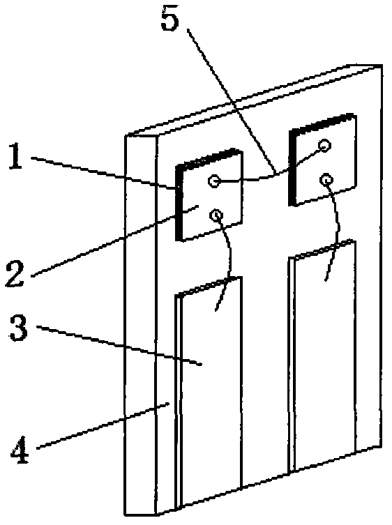
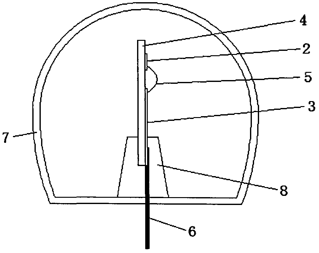
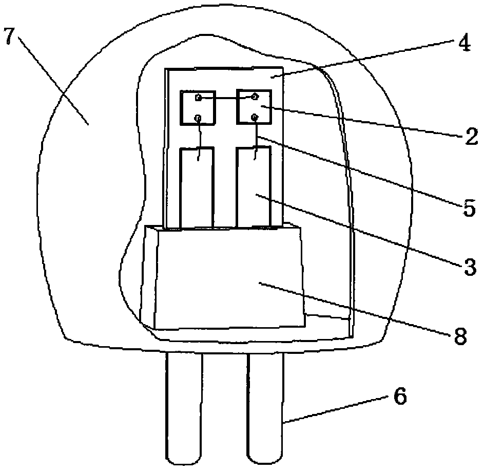
[0029] The present invention will be described in detail below with reference to the accompanying drawings. first reference figure 1 , which schematically shows the transparent bracket according to the first embodiment of the present invention. Such as figure 1 As shown, the main body of the transparent bracket is one or more pieces of transparent material 4, such as transparent glass or transparent film, and its thickness is about 0.4 mm to 5 mm. One or more LED chips 2 and one or more electrodes 3 are fixed on one side of the transparent glass or transparent film through a transparent die-bonding glue 1 . The electrical interconnection between chips and between chips and electrodes is realized through bonding wires 5 , which are preferably conventional bonding gold wires, and of course other metal or alloy power supply wires can also be used. It should be understood that although two LED chips connected in series are shown, the present invention is not so limited, and emb...


PUM


Abstract

The invention relates to an omnibearing lighting LED (light-emitting diode) packaging method and an LED packaging part. An LED chip and an electrode are firmly fixed on one or more pieces of transparent glass or transparent films by using a transparent crystal bonding adhesive, and then a transparent support on which the LED chip, the electrode and a welding line are fixed is erected and mounted in a transparent container. When the diode is electrified, the front surface of the LED chip on the erected transparent support can emit light normally, and the bottom part of the LED chip can also emit the brighter light through the transparent glass or the transparent films. By adopting the LED packaging method and the LED packaging part, the limitation that the brightest surface of an LED can not be displayed outwards due to a power supply conducting wire in the existing packaging technology can be eliminated, and the light extraction rate of the LED can be improved.

Description

technical field [0001] The present invention generally relates to packaging techniques for light emitting diodes, or LEDs. More specifically, the present invention relates to a packaging method for fixing LED chips and electrodes on transparent glass or transparent film by using transparent die-bonding glue, and an LED package using the method. Background technique [0002] Light-emitting diode (LED) is a light-emitting display device made of semiconductor materials that can directly convert electrical energy into light energy. It has the advantages of low power consumption and high brightness, so it is widely used in various electronic circuits, home appliances, Instruments and other equipment as indicators and display panels. Moreover, compared with ordinary incandescent lamps, light-emitting diodes have the advantages of small size, low calorific value, low power consumption, long life, fast response, and environmental protection, so they can also be widely used for ligh...

Claims


Application Information

Patent Timeline
Patent Type & Authority Applications(China)
IPC IPC(8): H01L33/00H01L33/48H01L33/56
CPCH01L2924/0002F21V3/0418F21V3/0481F21Y2101/02F21K9/90F21V29/248F21V29/004H01L2224/48137H01L2224/48091H01L33/48H01L25/0753F21V3/0436F21K9/135F21Y2111/001F21V29/58F21K9/232F21Y2115/10F21Y2107/00F21V3/12F21V3/062F21V3/061F21Y2109/00H01L2924/00014F21V3/02
Inventor 郑榕彬
Owner 郑榕彬
Learn More