
System and method for optimizing wireless network topology structure

A topology, wireless network technology, applied in the direction of wireless communication, electrical components, etc., can solve problems such as degradation, network quality degradation, inability to effectively utilize network resources, network carrying capacity, etc., to achieve the effect of improving network quality

Inactive Publication Date: 2011-07-20
北京创和世纪通讯技术股份有限公司
View PDF4 Cites 7 Cited by
  • Summary
  • Abstract
  • Description
  • Claims
  • Application Information

AI Technical Summary

Problems solved by technology

[0004] At present, operators mainly divide adjacent coverage cells in a certain region or administrative range into the same area according to the geographic location or administrative area of ​​the coverage cell or according to experience, and the coverage cells in this area perform data processing via the same lower-level control unit. For switching control, the adjustment of the wireless network topology only relies on the test of the covered cells to make local adjustments, or only when individual users generate complaints, local adjustments are made for this user, which does not play a fundamental role in improving the overall network quality Therefore, the existing wireless network topology often cannot effectively use network resources, resulting in a decrease in network carrying capacity, and a decrease in the quality of the network perceived by users. Sometimes it has to be improved by increasing network capacity, which increases the cost.

Method used


Image

  • System and method for optimizing wireless network topology structure
  • System and method for optimizing wireless network topology structure
  • System and method for optimizing wireless network topology structure

Examples


Embodiment Construction

[0022] The present invention will be further described below in conjunction with the accompanying drawings and specific embodiments.

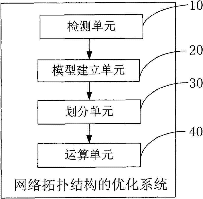
[0023] Please refer to figure 1 The system for optimizing wireless network topology of the present invention includes a detection unit 10, a model building unit 20, a division unit 30, and a computing unit 40, and the wireless network topology optimization system is used to optimize a wireless network topology 100 , the wireless network is not limited to any network, for example, the wireless network may be a 2G network, such as GSM, or a 3G network, such as WCDMA.

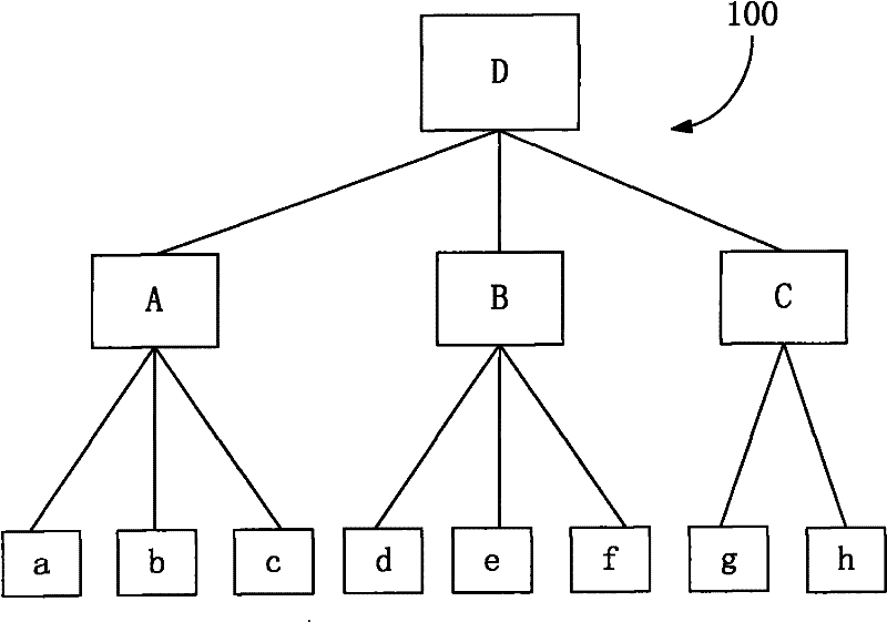
[0024] Please continue to refer figure 2 , the wireless network topology 100 includes a plurality of wireless receiving / transmitting devices (such as figure 2 Wireless receiving / transmitting equipment a-h in , a plurality of lower level control units (such as figure 2 in the lower level control unit A-C) and at least one higher level control unit (such as figure 2 In the hi...


PUM


Abstract

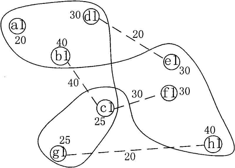
The invention discloses a method for optimizing a wireless network topology structure. The method comprises the following steps of: acquiring the number of switching times of a wireless terminal between wireless receiving equipment and wireless transmitting equipment, and multiplying the number of switching times by a signaling overhead coefficient to obtain a migration amount between the wireless receiving equipment and the wireless transmitting equipment; establishing corresponding points of the wireless receiving equipment and the wireless transmitting equipment; dividing the corresponding points into groups the number of which is the same as that of lower-layer control units; calculating the sum of network capacity parameters of corresponding points of each group and the sum of migration amounts of adjacent corresponding points of different groups in each dividing mode; and when the sum of the network capacity parameters is the most average and the sum of the migration amounts is the minimum, determining the dividing mode to be optimal. The invention also discloses a system for optimizing the wireless network topology structure. According to the method and the system, the signaling overhead brought by switching of the wireless terminal between the wireless receiving equipment and the wireless transmitting equipment is acquired, and the wireless receiving equipment and the wireless transmitting equipment are combined with the capacities of control units on each layer to optimize the wireless network topology structure, thereby improving the network quality at a macro level.

Description

technical field [0001] The invention relates to a network optimization system, in particular to a wireless network topology optimization system and method. Background technique [0002] With the rapid development of mobile communication, the number of communication service items continues to increase, and the number of wireless terminal users such as mobile phones and netbooks is also increasing. In order to expand competitive advantages and control costs at the same time, rational use of existing network resources has become the primary task of major operators. . At present, the wireless communication network has multiple coverage cells, and the users in each coverage cell realize wireless communication by exchanging data with the corresponding wireless receiving / transmitting equipment, and the wireless receiving / transmitting equipment can be a base station in the GSM network (BTS), Node B in the WCDMA network, etc., generally, the range covered by the multiple wireless re...

Claims


Application Information

Patent Timeline
Patent Type & Authority Applications(China)
IPC IPC(8): H04W24/02
Inventor 王兵侯少亭
Owner 北京创和世纪通讯技术股份有限公司
Learn More