
Temperature-measuring error correction method, equipment and system

An error correction and equipment technology, applied in the field of infrared shaft temperature detection, can solve the problems of inability to correct temperature measurement errors in time, low detection data accuracy, hidden dangers in railway transportation, etc., so as to reduce manpower, ensure safety, and correct temperature measurement. effect of error

Inactive Publication Date: 2011-07-27
BEIJING CTROWELL INFRARED TECHN
View PDF4 Cites 3 Cited by
  • Summary
  • Abstract
  • Description
  • Claims
  • Application Information

AI Technical Summary

Problems solved by technology

At present, when there is an error in the performance parameters of the probe, it is necessary for personnel to rush to the detection station to make corrections manually
In order to ensure the safety of personnel and the operation of trains, personnel and time scheduling must be carried out first, so that specific personnel can correct the performance parameters of the probe within a safe period of time. Existing solutions usually cannot correct temperature measurement errors in a timely manner.
[0006] Moreover, with the continuous speed-up of the current railway transportation, it is more and more inconvenient for personnel to carry out on-site maintenance operations, and because the environment where the probes are usually relatively harsh and the number is large, errors in the performance parameters of the probes occur from time to time. Some solutions are far from meeting the needs of timely correction of temperature measurement errors in practice, resulting in low accuracy of detection data obtained by the infrared shaft temperature detection system, poor system performance, and hidden dangers to railway transportation safety

Method used


Image

  • Temperature-measuring error correction method, equipment and system
  • Temperature-measuring error correction method, equipment and system
  • Temperature-measuring error correction method, equipment and system

Examples


Embodiment Construction

[0027] The technical solutions of the present invention will be clearly and completely described below in conjunction with the accompanying drawings of the present invention. Apparently, the described embodiments are only some of the embodiments of the present invention, not all of them. Based on the embodiments of the present invention, all other embodiments obtained by persons of ordinary skill in the art without creative efforts fall within the protection scope of the present invention.

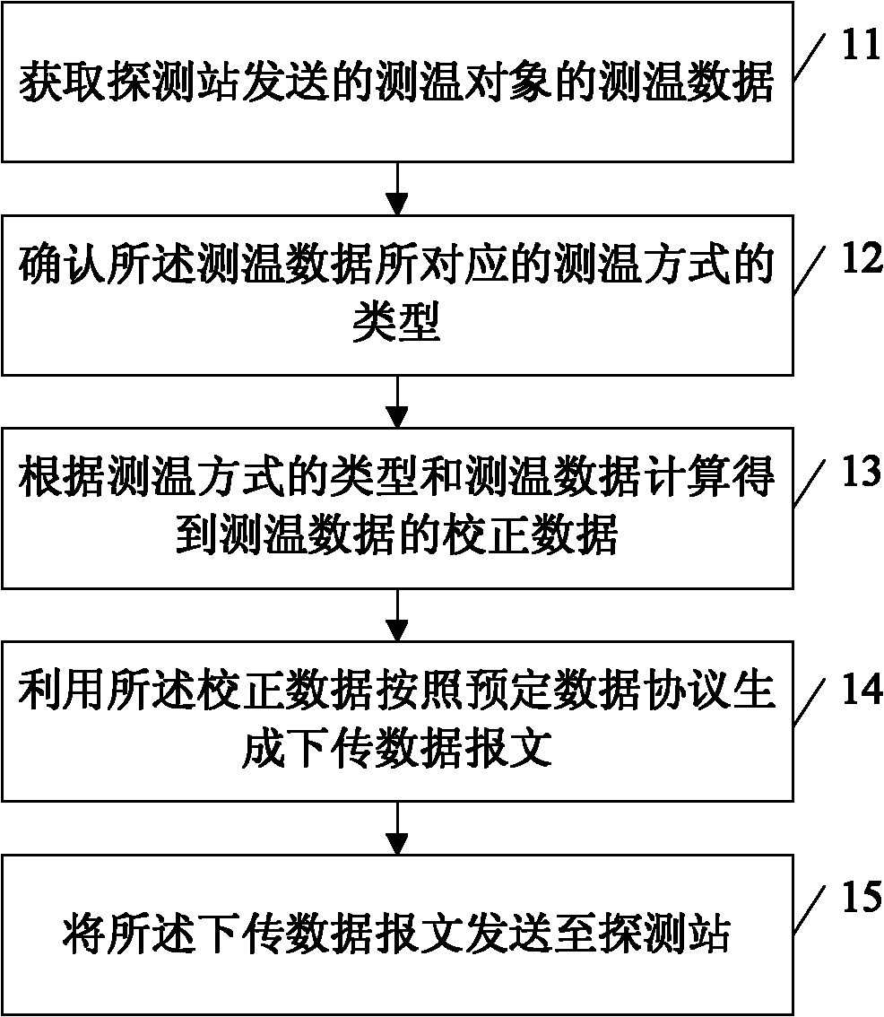
[0028] Embodiment 1 of the present invention provides a temperature measurement error correction method, see figure 1 , the method includes:

[0029] 11: Obtain the temperature measurement data of the temperature measurement object sent by the detection station;

[0030] 12: Confirm the type of temperature measurement method corresponding to the temperature measurement data;

[0031] 13: Calculate and obtain correction data of the temperature measurement data according to the type of the...


PUM


Abstract

The invention discloses a temperature-measuring error correction method, equipment and a system, relating to the technical field of infrared journal temperature detection. In the invention, temperature-measuring errors can be fast corrected in time, the temperature-measuring accuracy of a probe is corrected accurately, the accuracy rate of detected data is improved, the performance of an infraredjournal temperature detection system is improved and the safety of railway transportation is guaranteed. The temperature-measuring error correction method provided by the embodiment of the invention comprises the steps of: acquiring temperature-measuring data of a temperature-measuring object sent by a detection station; determining the type of a temperature-measuring mode corresponding to the temperature-measuring data; according to the type of the temperature-measuring mode and the temperature-measuring data, calculating to obtain correction data of the temperature-measuring data; utilizingthe correction data to generate download data messages according to a preset data protocol; and sending the download data messages to the detection station.

Description

technical field [0001] The invention relates to the technical field of infrared shaft temperature detection, in particular to a temperature measurement error correction method, device and system. Background technique [0002] Infrared shaft temperature detection system is an important facility for detecting hot shafts of vehicles, preventing hot shafts, ensuring the safety of railway transportation, and an important guarantee for improving transportation efficiency. [0003] Infrared shaft temperature detection system is usually composed of infrared detection station, road bureau monitoring center and repeating station and other parts. The detection station includes trackside equipment and indoor equipment, and completes the automatic detection of the axle temperature, wheelbase, speed and other information of the running train through the infrared probes installed on both sides of the rail, and obtains the detection data. The monitoring center of the railway bureau receive...

Claims


Application Information

Patent Timeline
IPC IPC(8): B61K9/04G01J5/00
Inventor 秦勤殷延超公茂财孙庆王新华张益关亮毕方勇田赏
Owner BEIJING CTROWELL INFRARED TECHN
Learn More