Semi-gear tension conveying device

A conveying device and half-gear technology, applied in the field of film laminating machines, can solve problems such as conveying, instability, and looseness

Active Publication Date: 2011-07-27
BOZHON PRECISION IND TECH CO LTD
View PDF4 Cites 5 Cited by
  • Summary
  • Abstract
  • Description
  • Claims
  • Application Information

AI Technical Summary

Problems solved by technology

[0002] When the film laminating machine is working, it needs to paste the film on the casing of the mobile phone, MP3 and other electronic products. At this time, the film used is in rolls, and the film is transported by the conveying mechanism for the film laminating machine. The conveying device includes a machine Shell, two rotatable rollers installed in the casing, one of the two rollers is the driving roller, which is used to connect with the power device to provide power, and the other is the driven roller, which is driven by the driving roller to rotate, driven The roller is hinged on the bracket, and the bracket is fixed on a rotatable shaft, so that the driven roller can rotate around the shaft. When conveying, the film is placed between the two rollers, and the film is clamped by the two rollers. The rear roller rotates to drive the film to move forward, and the force of the two rollers to clamp the film needs to be adjusted. If the clamping force is too large, the film will be damaged. If the clamping force is too small, the film cannot be clamped. For conveying, there is a clamping device on the conveying device, which is generally a transmission shaft with two eccentric wheels on it. The eccentric principle is used to squeeze the driven wheel and provide clamping force. However, the clamping device is When the tension force is provided, it is not stable enough, and it will loosen due to vibration and other reasons, so that the tension force acting on the driven roller changes.

Method used


Image

  • Semi-gear tension conveying device
  • Semi-gear tension conveying device
  • Semi-gear tension conveying device

Examples


Embodiment Construction

[0017] The following descriptions are only preferred embodiments of the present invention, and do not limit the scope of the present invention.

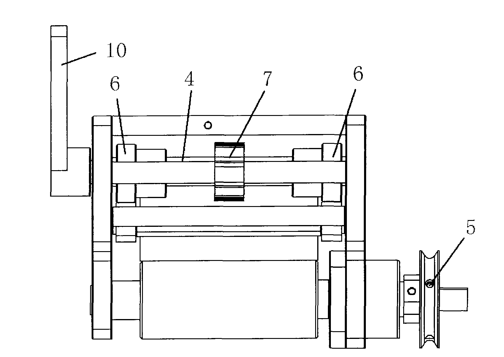
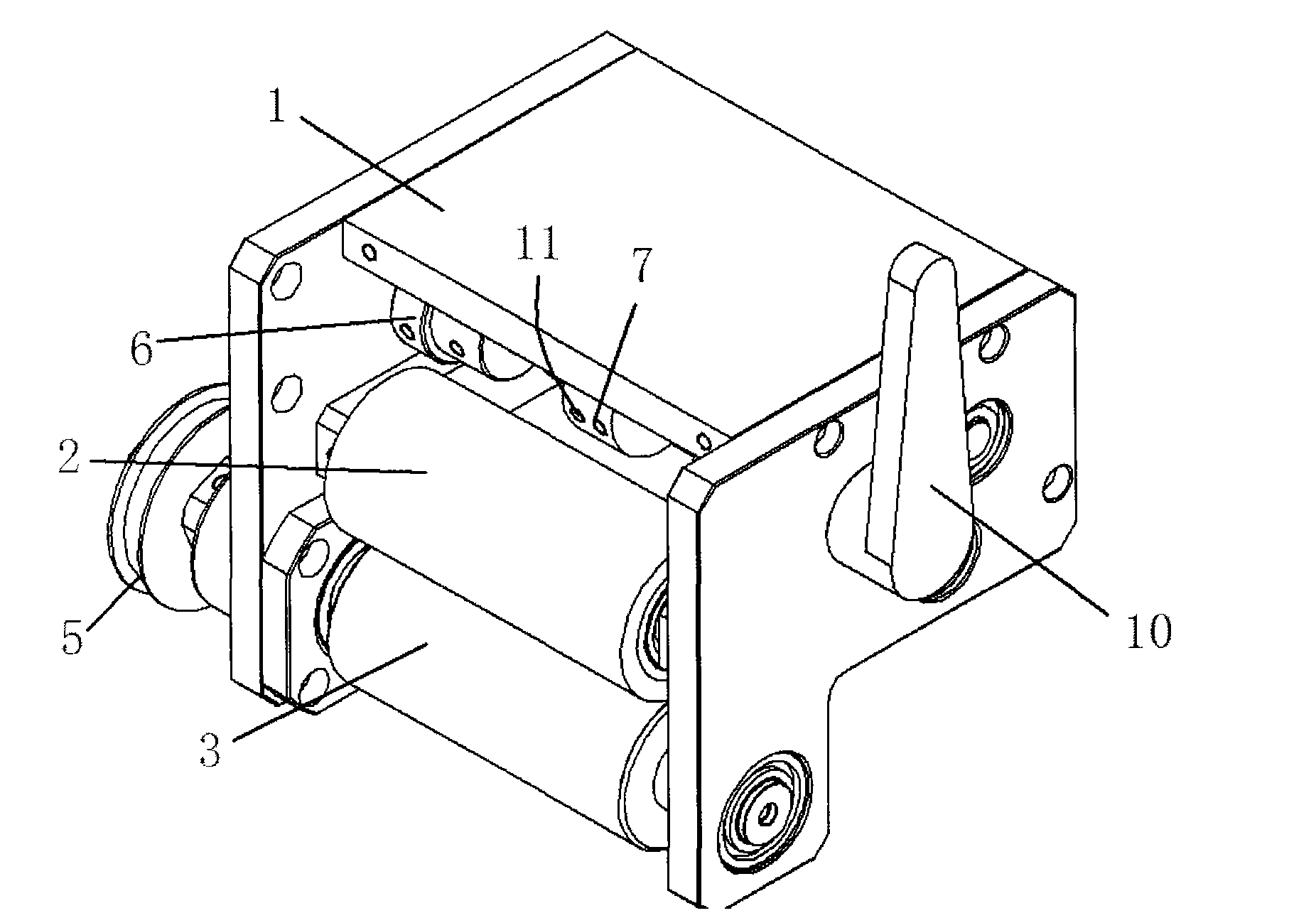
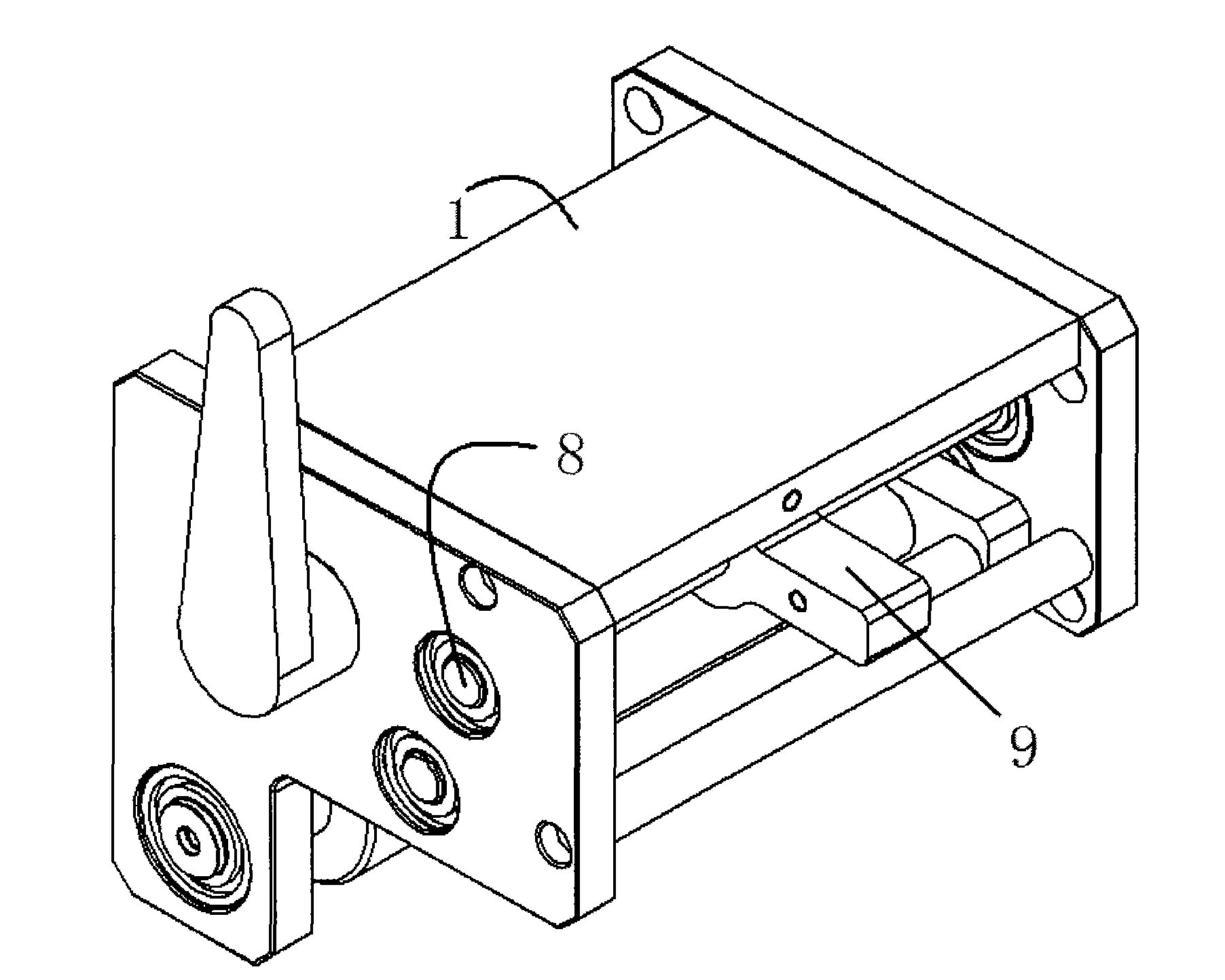
[0018] Examples, see attached Figures 1 to 5 The semi-gear tensioning conveying device includes a casing 1, a driven roller 2, a driving roller 3 and a drive shaft 4 are installed in the casing, a transmission pulley 5 is fixed at the end of the driving roller, and a transmission pulley 5 is fixed on the transmission shaft. There are two eccentric wheels 6; a half-gear 7 with half teeth 7a on the outer peripheral surface is fixed on the transmission shaft, and the casing also has a rotating shaft 8, which is mounted with clearance fit on the rotating shaft 8 The half gear handle 9, the size of the clearance is advisable that the half gear handle can rotate freely on the rotating shaft, and the front end of the half gear handle has a protrusion 9a that can be inserted into the teeth 7a of the half gear. The upper surface has an incl...


PUM


Abstract

The invention discloses a semi-gear tension conveying device comprising a shell. A driven roll, a driving roll and a transmission shaft are mounted in the shell; a transmission belt pulley is fixed at the end of the driving roll, two eccentric wheels are fixed on the transmission shaft; the two eccentric wheels can contact to the driven roll with the rolling of the transmission shaft, and allows the driven roll and the driving roll to be a compaction state; a semi-gear with a semi-tooth on the outer circumferential surface is also fixed on the transmission shaft; the shell is also provided with a rotating shaft, a semi-gear clamping stem is mounted on the rotating shaft in a clearance fit way, a protrusion capable of being inserted into the tooth of the semi-gear is arranged at the front end of the semi-gear clamping stem; and the upper surface of the protrusion is an inclined surface. The tension conveying device disclosed by the invention not only can be adjusted in the tension force, but also can keep the position in the use process without loosing phenomenon.

Description

Technical field: [0001] The invention relates to a film laminating machine used for laminating films on electronic products such as mobile phones and MP3s, and more specifically relates to a tensioning conveying device used on the film laminating machine. Background technique: [0002] When the film laminating machine is working, it needs to paste the film on the casing of the mobile phone, MP3 and other electronic products. At this time, the film used is in rolls, and the film is transported by the conveying mechanism for the film laminating machine. The conveying device includes a machine Shell, two rotatable rollers installed in the casing, one of the two rollers is the driving roller, which is used to connect with the power device to provide power, and the other is the driven roller, which is driven by the driving roller to rotate, driven The roller is hinged on the bracket, and the bracket is fixed on a rotatable shaft, so that the driven roller can rotate around the sh...

Claims


Application Information

Patent Timeline
IPC IPC(8): B65H23/26
Inventor 吕绍林汪炉生罗长江唐为付李先奇屈文武
Owner BOZHON PRECISION IND TECH CO LTD
Why Eureka
Try Eureka