
Movable support and movable support assisted method for erecting steel box beams through non-variable amplitude frame beam crane

A technology of girder erection crane and movable support, which is applied in the field of movable supports, can solve the problems of heavy design change workload of main girders and stay cables, large investment in dredging work in shoal areas, and high cost of strengthening steel box girders, etc., to achieve The effect of saving large-scale floating crane equipment and investment, reducing the cost of girder erecting cranes, and saving dredging costs

Active Publication Date: 2011-07-27
THE 5TH ENG MBEC
View PDF6 Cites 8 Cited by
  • Summary
  • Abstract
  • Description
  • Claims
  • Application Information

AI Technical Summary

Problems solved by technology

This scheme has the following disadvantages: 1. The risk that the floating crane cannot enter the site on time, and the cost of using the floating crane is relatively high; 2. Immediately after the installation of the beam section in the main tower area, the pier tops of temporary piers, auxiliary piers, and transition piers must be carried out. For the installation of the beam section, the beam section at the top of the pier needs to be manufactured in advance, and the manufacturing period is difficult to guarantee; 3. The dredging work in the shoal area requires a lot of investment
This scheme has the following disadvantages: 1. The cost of the luffing frame girder crane is about 3.5 million yuan more than that of the constant amplitude girder crane; Strengthening increases the cost; 3. The construction period of this scheme is longer

Method used


Image

  • Movable support and movable support assisted method for erecting steel box beams through non-variable amplitude frame beam crane
  • Movable support and movable support assisted method for erecting steel box beams through non-variable amplitude frame beam crane
  • Movable support and movable support assisted method for erecting steel box beams through non-variable amplitude frame beam crane

Examples


Embodiment Construction

[0019] The present invention will be described in further detail below in conjunction with the embodiments and with reference to the accompanying drawings.

[0020] A method for erecting a steel box girder with an auxiliary constant amplitude girder crane, the construction steps are as follows:

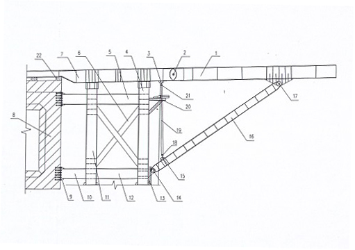
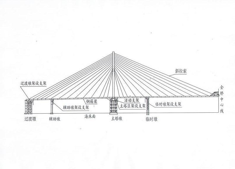
[0021] A: Installation of the beam section in the main tower area: first use the tower crane to assemble the erection bracket, the movable bracket and the beam erecting crane on one side of the beam section in the main tower area next to the pier of the main tower, and hoist the beam section in the main tower area to the movable bracket. Slide the girder erection crane and steel box girder longitudinally to the position of a beam section by means of jacking, then slide the girder erection crane to the hoisting position of the next beam section, continue to erect the remaining beam sections in the same way, and the beam section in the main tower area After the installation is completed...


PUM


Abstract

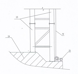
The invention discloses a movable support and a movable support assisted method through a non-variable amplitude frame beam crane. The method for erecting steel box beams comprises the following steps of: installing beam sections in a main tower region; installing standard beam sections; installing beam sections on the tops of temporary piers, auxiliary piers and transition piers; pressing side spans; and installing midspan closures. The movable support comprises slide beams, support main slides, left and right stand columns, upper and lower cross supports, a lifting system and counter pull cones. The method for erecting steel box beams has the advantages of reducing construction investment, reducing frame beam crane cost, erecting the steel beams in the manufacturing sequence, omitting large floating crane equipment and dredging expenses. The movable support has the advantages of assisting the non-variable amplitude frame beam crane to erect a plurality of sections of steel box beams in the main tower region and solving the problem that the non-variable amplitude frame beam crane hoists the beam sections to the support, and has a novel structure and definite stress. The movable support can be reused among all tower piers and has good economical and social benefits.

Description

technical field [0001] The invention relates to a construction method of a large bridge, in particular to a method for erecting a steel box girder with the aid of a movable support and a constant amplitude girder crane and a movable support thereof. Background technique [0002] As my country's infrastructure investment continues to increase, bridge construction has developed rapidly, especially cross-sea bridges have ushered in a construction climax. [0003] When building cross-sea bridges, the climate in coastal areas is changeable and the construction is difficult. Especially for the construction of cross-sea bridges in shallow talk areas, using existing technologies to erect steel box girders in shoal areas requires large investment and high risks. The commonly used steel box girder erection schemes include the following two construction schemes: (1) Floating crane auxiliary constant beam crane installation: use 1000t full-turn floating crane to install the beam section...

Claims


Application Information

Patent Timeline
IPC IPC(8): E01D21/00
Inventor 孙国光李述宝彭建萍叶绍其赵则锋龚国庆魏龙李洪锐王湘桥赵鲲鹏张海燕邓少锋
Owner THE 5TH ENG MBEC
Learn More