
Horizontal winding machine

A technology of horizontal winding machine and pay-off machine, which is applied in the direction of manufacturing coaxial cables and insulating conductors/cables. Unstable thread tension and other problems, to achieve the effect of adjustable row spacing, low equipment cost, and good winding effect

Active Publication Date: 2011-07-27
SHENYU COMM TECH
View PDF9 Cites 28 Cited by
  • Summary
  • Abstract
  • Description
  • Claims
  • Application Information

AI Technical Summary

Problems solved by technology

[0004] 1. The existing winding machine is a vertical structure, the operating space is small, and it is inconvenient for the operator to operate due to height restrictions
[0005] 2. The existing winding machine pays off by rotating the reel to achieve untwisting. The core wire is easily affected by centrifugal force, resulting in unstable pay-off tension. The pay-off speed of the winding machine is limited, thus affecting the production of ultra-fine coaxial cables efficiency
[0006] 3. The pay-off tension of the existing winding machine will change with the size of the coil on the reel during the pay-off process.
[0007] changes, resulting in instability of the plain line pay-off process
[0008] 4. The coiler of the existing winding machine adopts a wire arranging device to take up the wire, the row distance cannot be adjusted, and the take-up speed is not stable.
[0012] The package is completed by two mechanical equipment, the equipment cost is high, and the production efficiency is low

Method used

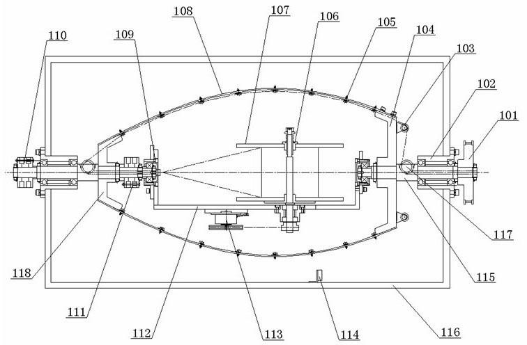
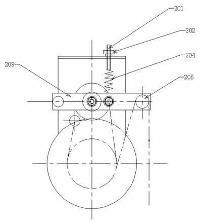

Image

  • Horizontal winding machine
  • Horizontal winding machine
  • Horizontal winding machine

Examples


Embodiment Construction

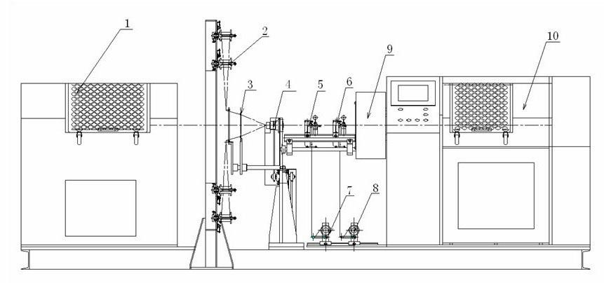
[0031] see figure 1 , a kind of horizontal winding machine that the present invention relates to, it comprises the untwisting pay-off machine 1 that is arranged in sequence along the horizontal direction, plain wire pay-off machine 2, line-incoming branch board 3, die hole 4, conductor taping device 5 , insulation taping device 6, drawing machine 9 and coiler 10, described untwisting pay-off machine 1, plain wire pay-off machine 2, incoming line splitter plate 3, die eye 4, conductor taping device 5, insulation The center lines of the tape wrapping device 6, the drawing machine 9 and the coiler 10 are on the same horizontal line, the first tape unwinding device 7 is arranged below the conductor tape wrapping device 5, and the second tape unwinding device 7 is arranged below the insulating tape wrapping device 6. Tape unwinding device 8. The core wire of the ultra-fine coaxial line is rotated under the action of the drawing machine 9, and the untwisted pay-off machine 1 passes...


PUM


Abstract

The invention relates to equipment for producing cables and wires, in particular to a winding machine for winding and belting during ultra-thin coaxial cable production. The horizontal winding machine comprises a backtwist unwinding machine (1), a tessellation line unwinding machine (2), an incoming line division board (3), a die hole (4), a conductor belting device (5), an insulation belting device (6), a leading machine (9) and a recoiling machine (10) which are arranged sequentially in the horizontal direction; the central lines of the backtwist unwinding machine (1), the tessellation line unwinding machine (2), the incoming line division board (3), the die hole (4), the conductor belting device (5), the insulation belting device (6), the leading machine (9) and the recoiling machine (10) are positioned on the same horizontal line; a first belt uncoiling device (7) is arranged below the conductor belting device (5); and a second belt uncoiling device (8) is arranged below the insulation belting device (6). The horizontal winding machine has the advantages of stably unwinding tessellation lines, finishing two working procedures of slantways belting and winding simultaneously, along with convenient operation, adjustable winding distance and high production efficiency.

Description

technical field [0001] The invention relates to a production equipment of cables and wires, in particular to a winding machine used for winding and tape-wrapping in the production of ultra-fine coaxial cables. Background technique [0002] Ultra-thin coaxial cable is a kind of tiny wire with excellent bending resistance and twist resistance. It is suitable for the connection of rotating, folding and other parts of portable equipment. It has good high-speed signal transmission and good shielding function. With the innovation of the market, the miniaturization of electronic products, the integration of signal transmission, etc., the enhancement of anti-interference, and the requirements of environmental resistance, the products of ultra-thin coaxial cables are more and more favored by the market. Recently, micro-coaxial cables have been widely used in notebook computers, medical equipment, digital cameras, and mobile phones. Ultra-thin coaxial cable products can guarantee hig...

Claims


Application Information

Patent Timeline
IPC IPC(8): H01B13/016H01B13/08
Inventor 汤晓楠
Owner SHENYU COMM TECH
Learn More