
Connector

A technology of connectors and connecting parts, which is applied in the direction of connection, fixed connection, contact parts, etc., can solve the problems of complex butt joint production process, low reliability, and peeling of metal layers, so as to improve processing and production process, enhance reliability, The effect of enhancing stability

Inactive Publication Date: 2013-10-23
CIVILIGHT SHENZHEN SEMICON LIGHTING
View PDF0 Cites 0 Cited by
  • Summary
  • Abstract
  • Description
  • Claims
  • Application Information

AI Technical Summary

Problems solved by technology

[0002] At present, when designing substrate connections in some electronic circuits, the main methods used are: using wire solder to connect; using terminal-to-terminal docking or using direct soldering between substrates to connect electrical or signal production processes, and many of the above connection methods All have deficiencies in varying degrees: the use of wire welding connection, because the metal layer as the solder formation surface is formed of copper and nickel, etc., so the adhesion to the metal layer as the solder exclusion surface is weakened, resulting in metal At the same time, in order to make the adhesion of the solder good, the solder film must be formed in advance, resulting in low productivity; the production process of using terminal to terminal is complicated; the cost is too high and the reliability is not high

Method used


Image

  • Connector
  • Connector
  • Connector

Examples


no. 1 example

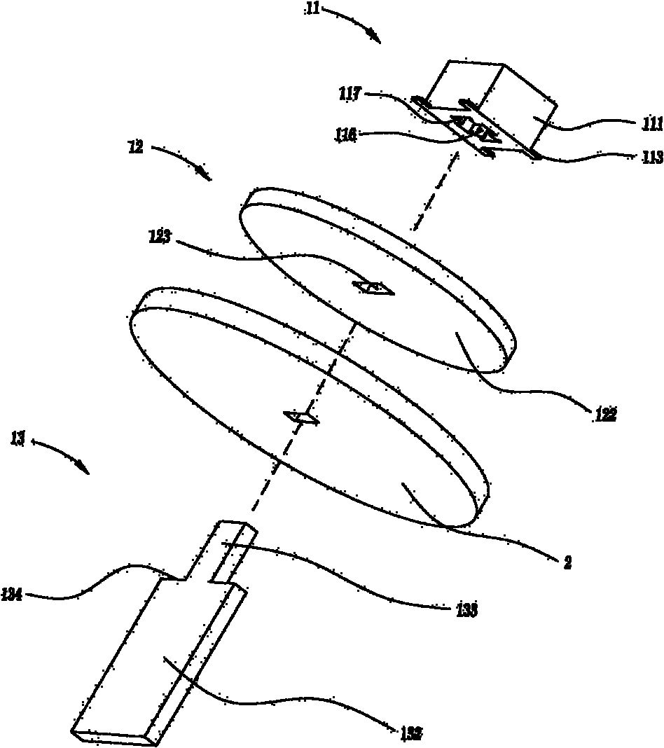
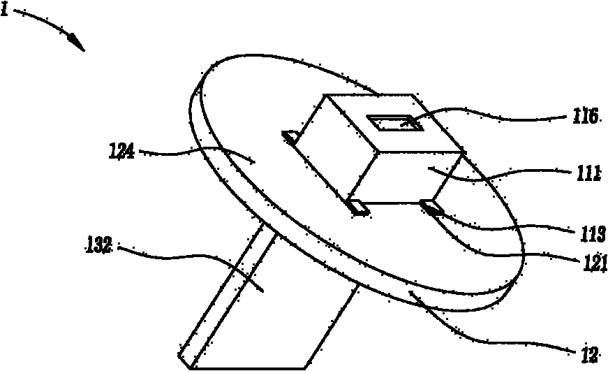
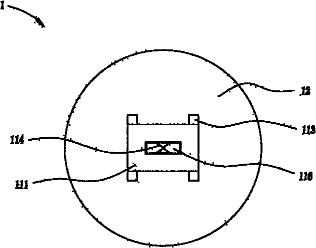
[0037] see Figure 1-Figure 3 , the embodiment of the present invention provides a connector 11 for connecting a mating substrate 12 and a rigid substrate 13, the connector 11 includes an insulating body 111, which accommodates at least one terminal 112, the terminal 112 and The docking substrate 12 is electrically connected, and at least one solder leg 113 corresponding to the terminal 12 is provided at the bottom of the insulating body 111 , and each solder leg 113 is welded on one side of the rigid substrate 13 In this way, the connector 11 is electrically connected to the rigid substrate 12 and the docking substrate 13, avoiding the connection between the substrates and the substrates in the prior art by soldering wires or connecting terminals to terminals, to a great extent It improves the processing and production process, saves time and labor; in addition, the connector 11 can be installed on any side of the rigid substrate 12, so that the design position of the connect...

no. 2 example

[0047] see Figure 7 As shown, the difference between the connector 11 of the present invention and the first embodiment is that: the connector 11 is provided with two terminals, and has two welding feet 113 welded on the rigid substrate 12 . Other structures are similar to those of the above-mentioned first embodiment, and will not be repeated here.

no. 3 example

[0049] see Figure 8 As shown, the difference between the connector 11 of the present invention and the first embodiment is that: the connector 11 is provided with three terminals, and has three welding feet 113 welded on the rigid substrate 12 . Other structures are similar to those of the above-mentioned first embodiment, and will not be repeated here.


PUM


Abstract

The invention provides a connector used for connecting a splicing substrate and a rigid substrate. The connector comprises an insulated main body which contains at least one terminal, the terminal is electrically connected with the splicing substrate; the bottom of the insulated main body is provided with at least one welding leg correspondingly conducted with the terminal, and the welding legs are welded at one face of the rigid substrate; and a connection device is electrically connected with the rigid substrate and the splicing substrate through the connector. By means of the connector provided by the invention, the fact that the substrates are connected by wire soldering tin or the terminals are spliced in the prior art is avoided, the processing production process is improved to a great extend and time and labor are saved.

Description

technical field [0001] The invention relates to the field of electrical circuits, in particular to the improvement of a connector connecting multiple circuit substrates. Background technique [0002] At present, when designing substrate connections in some electronic circuits, the main methods used are: using wire solder to connect; using terminal-to-terminal docking or using direct soldering between substrates to connect electrical or signal production processes, and many of the above connection methods All have deficiencies in varying degrees: the use of wire welding connection, because the metal layer as the solder formation surface is formed of copper and nickel, etc., so the adhesion to the metal layer as the solder exclusion surface is weakened, resulting in metal At the same time, in order to make the adhesion of the solder good, the solder film must be formed in advance, resulting in low productivity; the production process of using terminal to terminal is complicate...

Claims


Application Information

Patent Timeline
Patent Type & Authority Patents(China)
IPC IPC(8): H01R13/02H01R13/46H01R12/52H01R12/55H01R12/71H01R12/73
Inventor 易磊
Owner CIVILIGHT SHENZHEN SEMICON LIGHTING
Learn More