A mode selection waveguide laser

A technology of lasers and modes, which is applied in the direction of lasers, gas laser parts, laser parts, etc., can solve the problem of not describing the length and size information of the slit

Active Publication Date: 2011-07-27
ルクシナーリミテッド
View PDF12 Cites 12 Cited by
  • Summary
  • Abstract
  • Description
  • Claims
  • Application Information

AI Technical Summary

Problems solved by technology

But does not describe the slit length on the o

Method used


Image

  • A mode selection waveguide laser
  • A mode selection waveguide laser
  • A mode selection waveguide laser

Examples


Embodiment Construction

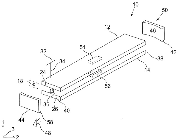
[0038] attached figure 1 A mode selective laser is shown, indicated with reference numeral 10 . Laser 10 includes a pair of elongated rectangular planar electrodes 12, 14 made of a conductive metal, such as aluminum. The planar dimensions of the electrodes 12 , 14 determine the size of the discharge region 16 formed between them, and thus determine the output power of the laser 10 . For 100w CO 2 For a laser, the electrodes may be approximately 480 mm long and 45 mm wide. The electrodes 12, 14 are typically adapted to include one or more coolant channels (not shown) through which water passes.

[0039] The electrodes 12, 14 are spaced apart by the height of a waveguide, or a gap 18 between the electrodes. Usually the height of the gap 18 is 1 mm to 4 mm, and in a preferred embodiment, the height is in the range of 1.3 mm to 2.8 mm. The electrodes 12 , 14 are spaced apart by a predetermined height 18 .

[0040] The discharge region 16 is then confined within the first and...


PUM

PropertyMeasurementUnit
Heightaaaaaaaaaa
Heightaaaaaaaaaa

Abstract

A mode selection laser comprises a recess which is formed in the surface of an electrode in a waveguide in the laser. The recess provides a region of free space propagation within the waveguide which preferentially selects the lowest order mode. A mode selective RF excited CO2slab laser may be constructed, having a stable resonator in the waveguide dimension and a negative branch unstable resonator in the non-waveguide dimension. The position and size of the recess is considered to provide low order mode selection.

Description

technical field [0001] The present invention relates to mode selection techniques for lasers, and in particular, without limitation, to radio frequency excited slab waveguide CO 2 A laser in which a recess is provided on the surface of the waveguide to provide a free-space propagation region within the waveguide. The position and size of the recess can be varied to provide mode selection. Background technique [0002] A typical RF-excited slab waveguide CO 2 laser. Wherein, a pair of rectangular planar electrodes with exposed light reflecting surfaces are distributed separately, and their spatial structure is set to guide light on a plane perpendicular to the reflecting surfaces, such as a waveguide. Light parallel to the reflective surface is unconfined except through the resonator mirrors located at the ends of the electrodes. The structure of the resonator is designed as a negative branch unstable resonator within the non-waveguide dimensions. Stabilized resonators a...

Claims


Application Information

Patent Timeline
IPC IPC(8): H01S3/223H01S3/098H01S3/03
CPCH01S3/08045H01S3/08059H01S3/0315H01S3/08081H01S3/2232H01S3/0385
Inventor 杰森·罗伯特·李加文·艾伦·詹姆斯·马基利
Owner ルクシナーリミテッド
Why Eureka
Try Eureka