Distributed feedback light waveguide laser

A distributed feedback, optical waveguide technology, applied in the field of optoelectronics, can solve the problems of complex phase-shift grating, low yield, and difficulty in manufacturing DFB optical waveguide lasers.

Inactive Publication Date: 2005-02-23
TSINGHUA UNIV
View PDF1 Cites 11 Cited by
  • Summary
  • Abstract
  • Description
  • Claims
  • Application Information

AI Technical Summary

Problems solved by technology

At present, DFB optical waveguide lasers are relatively mature in theory, but in terms of production, the production of phase shift gratings is relati

Method used


Image

  • Distributed feedback light waveguide laser
  • Distributed feedback light waveguide laser
  • Distributed feedback light waveguide laser

Examples


Embodiment Construction

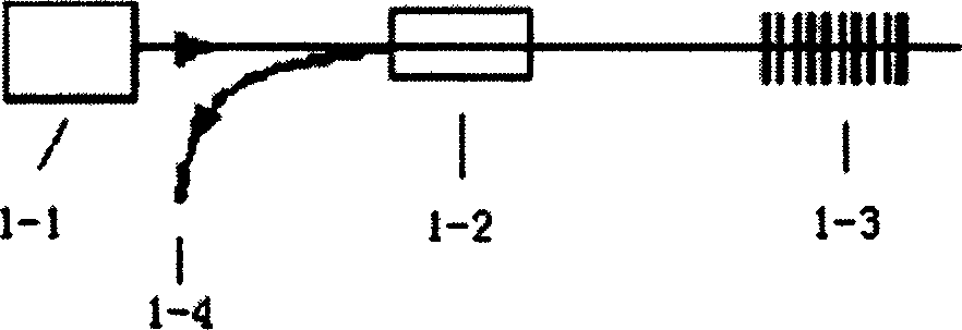
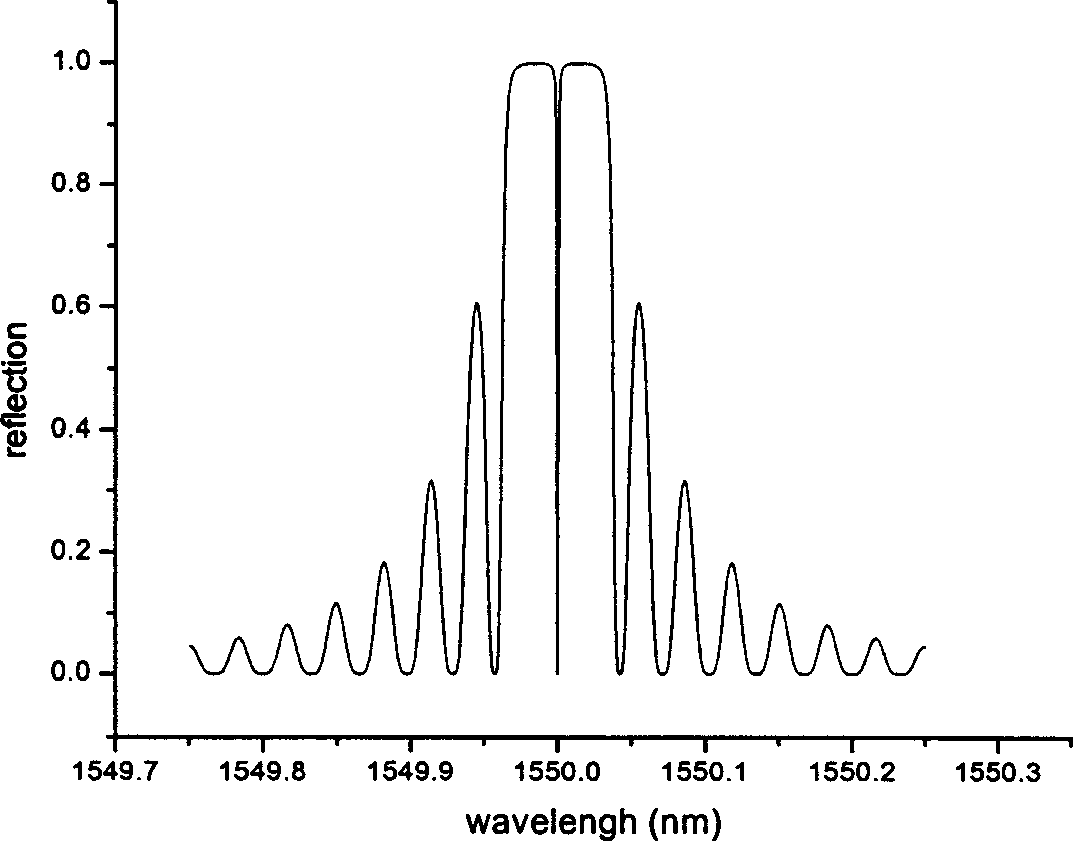
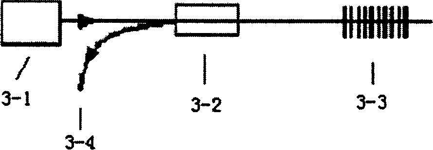
[0050] The manufacturing method of the DFB fiber laser based on the equivalent phase shift sampling fiber grating of the present invention is divided into two parts: one is the design and manufacture of the equivalent phase shift sampling fiber grating, and the other is the manufacturing of the DFB fiber laser. Concrete implementation example is described in detail as follows in conjunction with accompanying drawing:

[0051] 1. Design and manufacture of equivalent phase-shift sampling fiber grating

[0052] This experiment is made with a chirped template. According to the literature, to compensate for the chirp of the grating period introduced by the template at the -1 level peak, it is necessary to compensate the grating period chirp caused by the template by changing the sampling period of the grating. Specifically is the formula z n + a z n 2 = n ...


PUM


Abstract

In this invention, in the minus or plus 15%area from the center of the sampling Prague grating which is etched on the light waveguide, on of the sampling period is jumping, while other sampling period is keeping unchanged. The jumped period is 1.4-1.6 or 0.4-0.6 times of the original. The sampling Prague grating makes the respective reflecting peak generate similar slit of the normal grating. The period of this grating possesses the property of linear chirp. When the period jumped to 1.5 or 0.5 times of the original, the -1 level chirp reflecting peak is about to zero.

Description

technical field [0001] The invention belongs to the technical field of optoelectronics and relates to a distributed feedback optical waveguide laser, in particular to the design and manufacture of a single longitudinal mode and single polarization DFB fiber laser. technical background [0002] There are many types of lasers, but their manufacturing principles are basically the same. Most of them are composed of three parts: excitation system, laser material and optical resonator. Due to the development of semiconductor laser technology and optical communication, semiconductor-pumped optical waveguide lasers doped with gain substances have developed rapidly in recent years because of their excellent performance. Optical waveguide lasers mainly include fiber lasers and planar optical waveguide lasers. Distributed feedback (Distributed Feedback, DFB) optical waveguide laser is one of the most important ones. DFB optical waveguide lasers have many excellent characteristics: na...

Claims


Application Information

Patent Timeline
IPC IPC(8): H01S3/063H01S3/067H01S3/08H01S3/0941H01S3/16
Inventor 陈向飞姜典杰戴一堂谢世钟
Owner TSINGHUA UNIV
Why Eureka
Try Eureka