Die for S-shaped bending of copper bars

A mold and flat bending technology, which is applied in the field of molds for bending copper bars into S shapes, to achieve the effects of high processing precision, fast processing, and easy withdrawal

Active Publication Date: 2011-08-03
JIANGSU JINFANGYUAN CNC MACHINE CO LTD
View PDF3 Cites 14 Cited by
  • Summary
  • Abstract
  • Description
  • Claims
  • Application Information

AI Technical Summary

Problems solved by technology

[0002] In the prior art, the flat bending mold of the busbar bending machine can be bent along the width direction of the copper bar to meet the requirements of different bending forms of the copper bar in the power industry; One bend can be made. When the distance between the two bends in the width direction of the copper bar is small, ordinary flat bending molds cannot achieve a small distance through two bends.

Method used


Image

  • Die for S-shaped bending of copper bars
  • Die for S-shaped bending of copper bars
  • Die for S-shaped bending of copper bars

Examples


Embodiment Construction

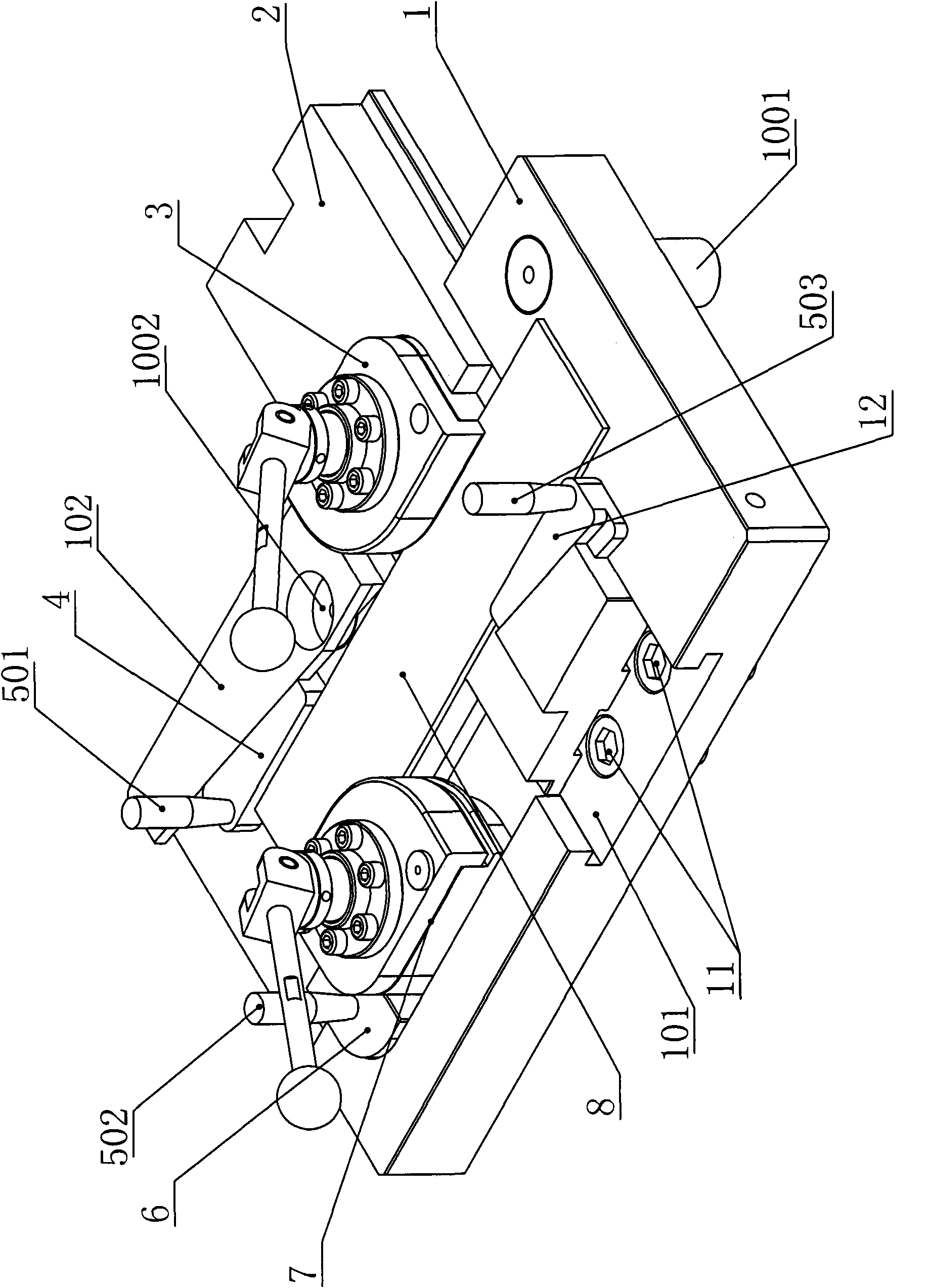
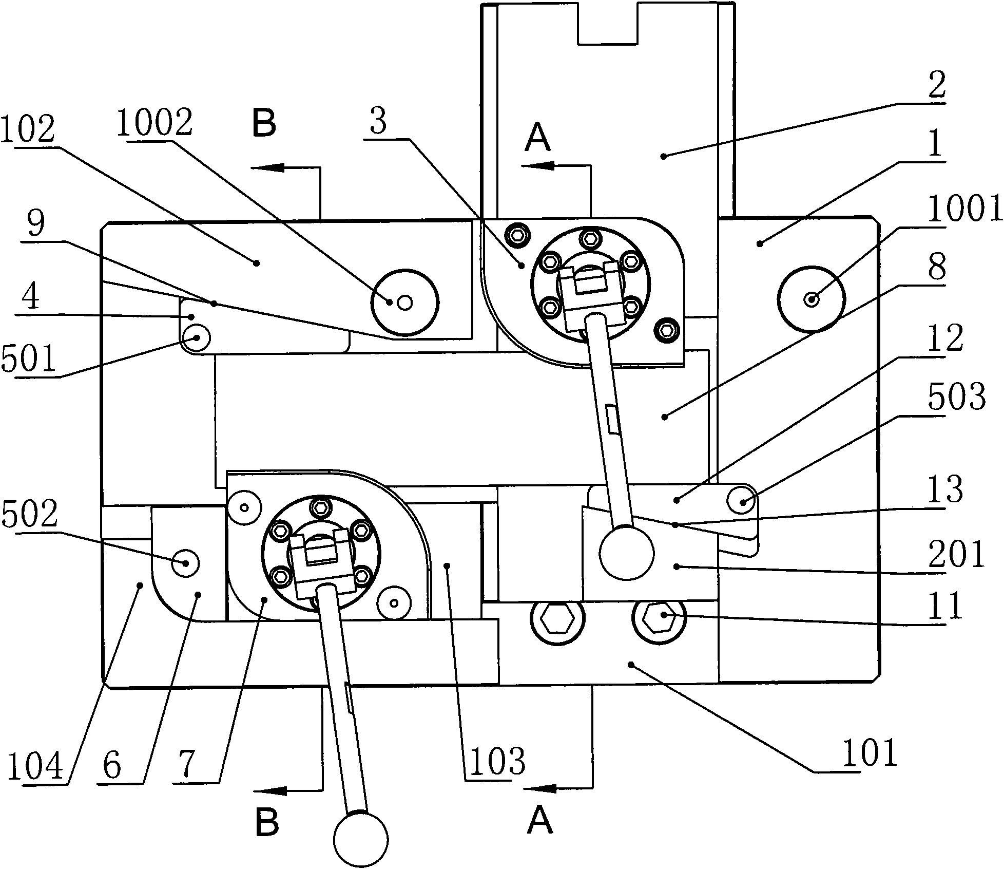
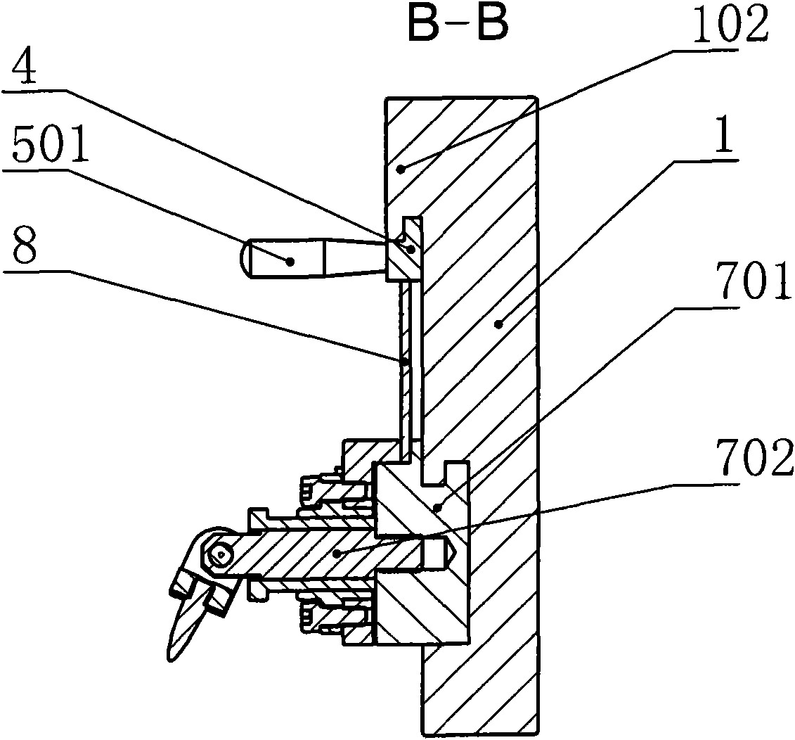
[0018] Such as Figure 1-5 As shown, it is a mold for S-shaped bending of copper bars, and a first chute 101 is provided in the front and rear direction of the pallet 1, and the first chute 101 runs through from the front side of the pallet 1 to the rear side of the pallet 1. In the first chute 101, a support plate 2 is arranged, and the support plate 2 can slide back and forth along the first chute 101; the support plate 2 is fixed with the first flat bending die 3 with screws; 101 is vertically provided with a second chute 103, the second flat bending die 7 is arranged in the second chute 103, one end of the second chute 103 is connected with the first chute 101, and the supporting plate 1 is connected with the second chute 103 The other end of the corresponding end is provided with a limiter 104; a backing plate 6 is provided between the limiter 104 and the second flat bending die 7; when the second flat bending die 7 is installed in the second chute 103, it is located On ...


PUM


Abstract

The invention relates to a die for S-shaped bending of copper bars in the field of bus processing dies. A first chute is formed in the front and rear direction of a backing plate of the die, a support plate is matched and arranged in the first chute, and a first flat bending die is fixed on the support plate; the backing plate is also provided with a second flat bending die on the lateral surfaceof the first chute, the support plate is provided with a first support part corresponding to the first flat bending die, one side of the first support part towards the first flat bending die is a first wedge-shaped surface, and a first wedge block is matched with the first wedge-shaped surface; the support plate is provided with a second support part corresponding to the second flat bending die, one side of the second support part towards the second flat bending die is a second wedge-shaped surface, and a second wedge block is matched with the second wedge-shaped surface; and gaps capable of clamping the copper bars in the width direction are reserved between the first wedge block and the first flat bending die and between the second wedge block and the second flat bending die. The devicecan bend the copper bars into S shape, is quick and convenient for processing, and has high processing precision; and the device can be used in bus production.

Description

technical field [0001] The invention relates to a busbar processing mold, in particular to a mold for bending copper bars into an S shape. Background technique [0002] In the prior art, the flat bending mold of the busbar bending machine can be bent along the width direction of the copper bar to meet the requirements of different bending forms of the copper bar in the power industry; One bend can be made. When the distance between the two bends in the width direction of the copper bar is small, ordinary flat bending molds cannot achieve a small distance through two bends. Contents of the invention [0003] The object of the present invention is to provide a mold for S-shaped bending of copper bars, so that the copper bars can be bent into an S-shape at one time in the width direction of the copper bars. [0004] The object of the present invention is achieved in this way: the mold for S-shaped bending of copper bars includes a supporting plate, and a first chute is provi...

Claims


Application Information

Patent Timeline
Patent Type & Authority Applications(China)
IPC IPC(8): B21D5/06B21D37/10
Inventor 吴宏祥叶敬春佘萍王其柱李晓春
Owner JIANGSU JINFANGYUAN CNC MACHINE CO LTD
Why Eureka
Try Eureka