Positioning method for fixing T steel through magnetic force

A technology of magnetic fixing and positioning method, which is applied in the processing of building materials, the preparation of building components on site, the connection of formwork/template/work frame, etc. Complicated problems, to achieve the effect of preventing slurry leakage, facilitating mold removal, and simple operation

Active Publication Date: 2011-08-03
CHINA RAILWAY 24TH BUREAU GRP +1
View PDF8 Cites 11 Cited by
  • Summary
  • Abstract
  • Description
  • Claims
  • Application Information

AI Technical Summary

Problems solved by technology

Although this fixing method is firm, it destroys the rigidity of the steel mold, and the operation is more complicate

Method used


Image

  • Positioning method for fixing T steel through magnetic force
  • Positioning method for fixing T steel through magnetic force
  • Positioning method for fixing T steel through magnetic force

Examples


Embodiment 1

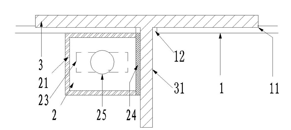
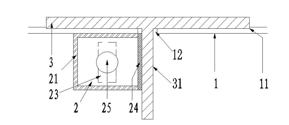
[0027] see Figure 1-2 , in the first embodiment, the magnetic fixing device is a magnetic box 2 . The magnetic box 2 is composed of a box body 21 , a rotating fixture 22 , a magnet 23 and a magnetic switch 25 . Wherein, the magnet 23 may be a bar-shaped or cylindrical permanent magnet. The box body 21 is fixedly welded on the outer side of the T steel 3 near the hole 12. When the T steel 3 is inserted into the steel mold 1, one side of the box body 21 is attached to the web 31 of the T steel 3, and the box body 21 is connected to the T steel 3 The attached side is the base 24 of the magnetic box 2 . The material of the base 24 is a soft magnetic material. The so-called soft magnetic material is a magnetic material with low coercivity for magnetic induction and magnetic polarization. It can achieve maximum magnetization with the smallest external magnetic field, and is easy to magnetize and demagnetize. Such as iron-silicon alloy (silicon steel sheet) and various soft ferri...

Embodiment 2

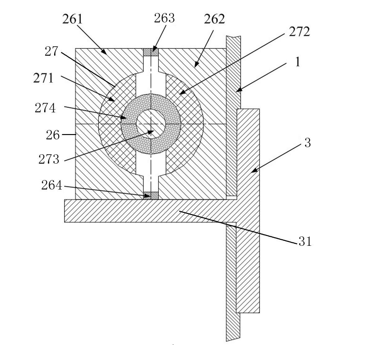
[0032] see Figure 3-4 As shown, in the second embodiment, the magnetic box 2 is composed of a shell 26 with a cylindrical cavity inside and a core 27 movably fitted in the shell 26 . Wherein, the housing 26 is a rectangular parallelepiped-shaped Hafur structure, which is composed of magnetically permeable half bodies 261 , 262 and two non-magnetically permeable bodies 263 , 264 . The inner sides of the two magnetically conductive halves 261, 262 have arc-shaped grooves. The upper and lower raised ends of the grooves are the end faces in the usual Hafur structure. The ends of the two magnetically conductive halves 261, 262 are Two non-magnetic conductors 263, 264 are fixedly connected to form a whole. The split plane of the Harfur structure is perpendicular to the web 31 of the T-steel 3 . The core 27 is composed of a magnet 273 and magnetically conductive rotors 271, 272 symmetrically fixed on the outside of the two magnetic poles of the magnet 273. The two rotors 271, 272 ...

Embodiment 3

[0037] see Figure 5 In this embodiment, the structure of the magnetic box 2 is basically the same as that of the first embodiment, and it also has a base 24 that is easily magnetized. The difference is that the permanent magnet and the rotating device are replaced by an electromagnet 275, and the electromagnet 275 is fixed in the box body 21 , by starting the switching power supply 276 to generate a magnetic field to magnetize or demagnetize the base 24, the effect of magnetic attraction and positioning of the above-mentioned magnet 23 can also be achieved. This kind of structure can be mainly applied in large steel components, especially when the permanent magnet cannot meet the magnetic force requirements.

[0038] For the connection positioning structures of the above three embodiments, the calculation of the connection strength is as follows:

[0039] During the pouring process, T-steel 3 is mainly subjected to three forces, namely, the vibration force of the vibrating r...


PUM

PropertyMeasurementUnit
Remanenceaaaaaaaaaa
Saturation magnetic inductionaaaaaaaaaa

Abstract

The invention relates to the technical field of dies in T beam pouring construction, in particular to a positioning method for fixing T steel through magnetic force. The method is characterized by comprising the following steps of: pre-welding a magnetic force device on one side of a long hole outside a steel die; after a web of the T steel is inserted into the long hole, generating a magnetic field by using the magnetic force device or changing the direction of the magnetic field to adsorb the exposed part of the T steel web so as to fix and position the T steel; and making the magnetic field of the magnetic force device disappeared or changing the direction of the magnetic field to separate the T steel from the steel die. The method has the advantages that: by arranging the magnetic force device and using a principle that a magnet magnetically attracts ferric materials, a hole is not required to be punched, and the T steel and the steel die can be positioned and fixed through the magnetic force, so that slurry leakage can be effectively prevented, and the stiffness and appearance of the steel die are not damaged simultaneously; and the method is easy to operate, and the die is convenient to disassemble.

Description

technical field [0001] The invention relates to the technical field of molds in T-beam pouring construction, in particular to a positioning method for magnetically fixing T-steel. Background technique [0002] At present, in the casting construction of the steel mold, bolts are usually used to connect the steel mold and the T steel. Several bolt holes are set on the steel mold, and the position of the T steel corresponding to the steel mold is also matched with the bolt holes. The steel mold and the T steel are connected by bolts. Steel is held together. Although this fixing method is firm, it destroys the rigidity of the steel mold, and the operation is also more complicated, and it is easy to leak slurry, and it is extremely inconvenient to remove the mold, and it also affects the appearance. Contents of the invention [0003] The purpose of the present invention is to provide a kind of positioning method for magnetically fixing T-steel according to the deficiencies of ...

Claims


Application Information

Patent Timeline
IPC IPC(8): E04G17/04E04G21/00E04G13/04
Inventor 吴承张王巍钱明剑
Owner CHINA RAILWAY 24TH BUREAU GRP
Why Eureka
Try Eureka