Linear transmission reciprocating-type internal combustion engine

A linear transmission, reciprocating technology, applied in the direction of machines/engines, mechanical equipment, etc., can solve problems such as low transmission efficiency, power damage, cylinder wear, etc., to achieve the effect of reducing power loss, prolonging service life, and ensuring reciprocating motion

Inactive Publication Date: 2011-08-03
郭革委
View PDF6 Cites 0 Cited by
  • Summary
  • Abstract
  • Description
  • Claims
  • Application Information

AI Technical Summary

Problems solved by technology

[0006] The purpose of the present invention is just to overcome the defects and deficiencies of the above-mentioned existing reciprocating internal combustion engine, such as power damage, cylinder wear, and low transmission efficiency, to provide a torque dead point, unbiased cylinder phenomenon, avoid cylinder wear, transmission Efficient linear drive reciprocating internal combustion engine

Method used


Image

  • Linear transmission reciprocating-type internal combustion engine
  • Linear transmission reciprocating-type internal combustion engine
  • Linear transmission reciprocating-type internal combustion engine

Examples


Embodiment 1

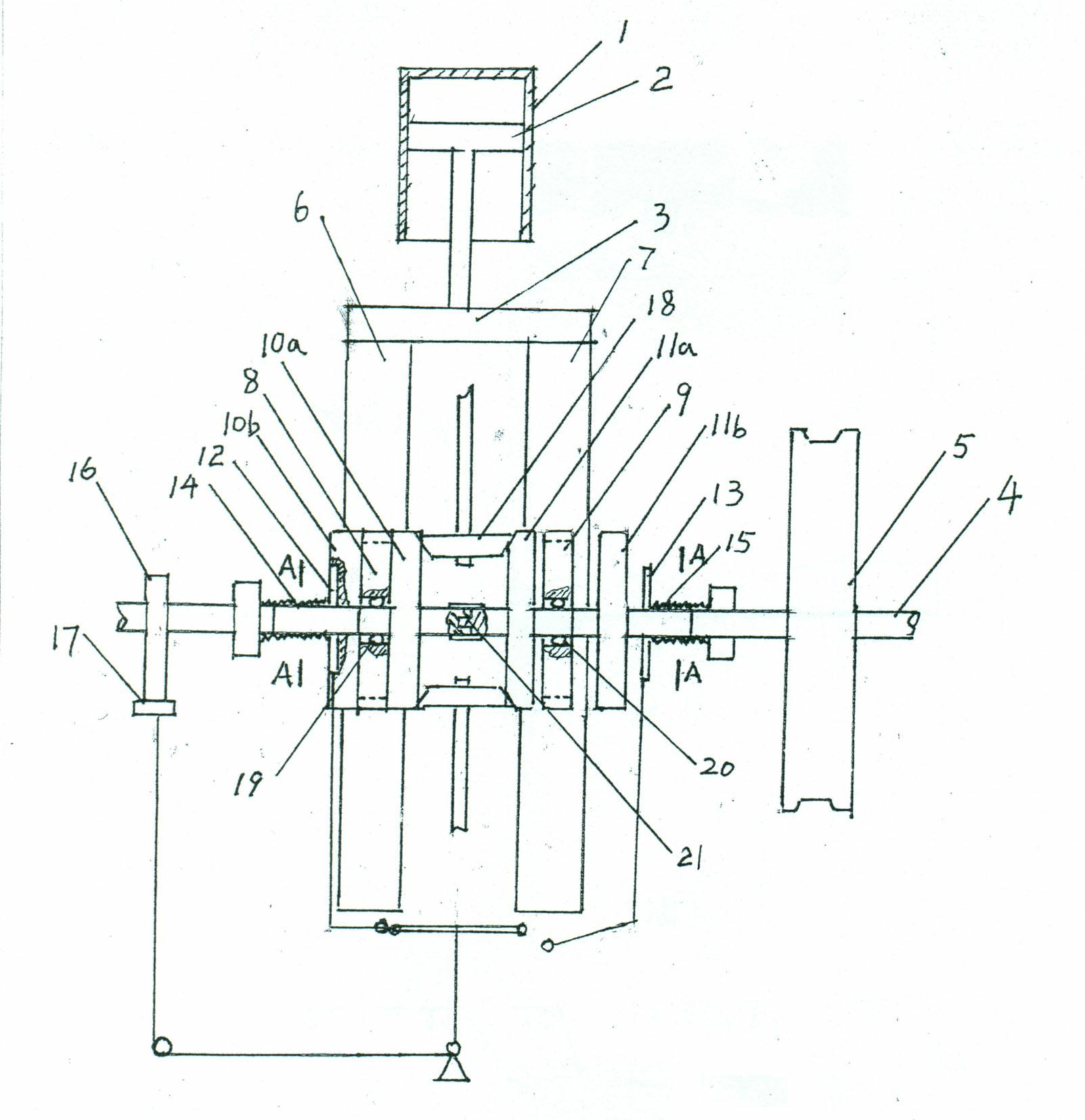
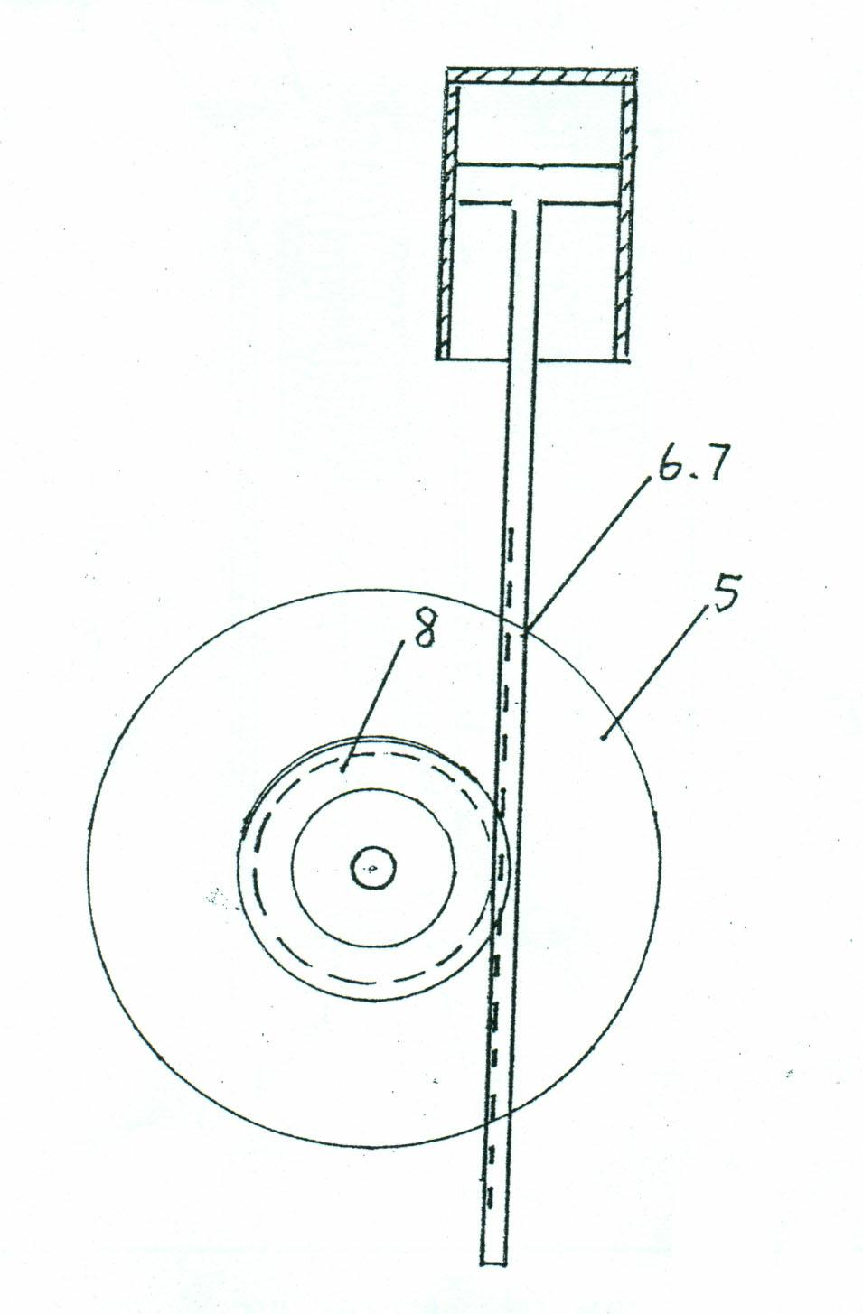
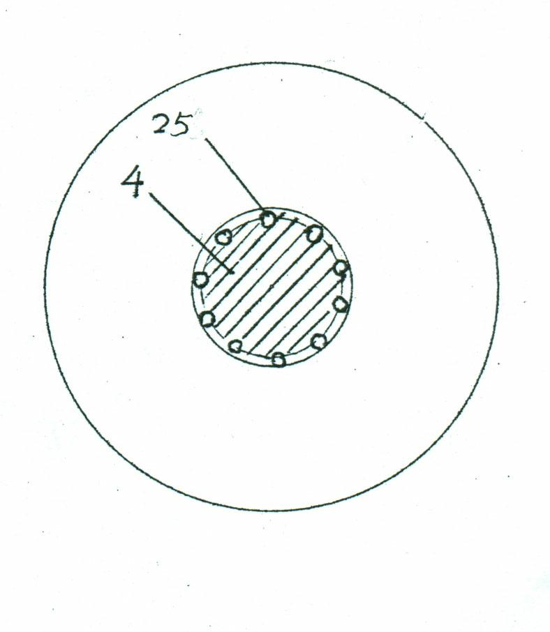
[0017] Example 1 see figure 1 , figure 2 , image 3 , Figure 5 , a reciprocating internal combustion engine, including a cylinder 1, a piston 2, a piston connecting rod 3, a transmission shaft 4, and a flywheel 5. The technical feature of this embodiment is that the piston connecting rod 3 connected to the piston 2 is set as two The structure of the transmission rack 6 and the reset rack 7 of the rack section, the rack section 6 meshes with the transmission gear 8 arranged on the transmission shaft 4; and a reset gear 9 is provided to mesh with the rack section 7; the transmission gear 8 and The reset gears 9 are floatingly connected to the transmission shaft 4, and the transmission shaft 4 is two coaxial sections, which are connected by a shaft connector 21; a pair of transmission flywheels 10a, 10a, 10b and a pair of reset pressure flywheels 11a, 11b, the transmission pressure flywheels 10a, 10b and reset pressure flywheels 11a, 11b can slide axially on a chute segment ...

Embodiment 2

[0019] Example two see Figure 4 , the present invention sets the rack section on the piston connecting rod 3 so that two adjacent vertical surfaces all have rack sections, and sets the cylinders 1 side by side as four cylinders A, B, C, and D, and the piston connecting rod 3 is 3a, 3b, 3c, 3d four; transmission gear 8 is respectively set to 8a, 8b, 8c, 8d four, and one side rack section of piston connecting rod 3a, 3b, 3c, 3d is respectively connected with the corresponding transmission The gears 8a, 8b, 8c, 8d are meshed, and the other rack segment is meshed with three cylinder linkage gears 22, 23, 24 meshed in series.

[0020] The working principle of this embodiment is that when the piston connecting rod 3a goes down, the exhaust port of cylinder A is closed, the air inlet is opened, and cylinder A starts to intake air; the intake and exhaust ports of cylinder B are closed, piston B starts to move upward, and the compression stroke begins ; while the C cylinder is in the...


PUM


Abstract

The invention relates to a linear transmission reciprocating-type internal combustion engine. According to the invention, a piston connecting rod (3) which is connected with a piston (2) is arranged in a structure with a rack bar; the rack bar is meshed with a transmission gear (8) and a restoration gear (9) which are arranged on the transmission shaft (4); a restoration mechanism is arranged and is meshed with the restoration gear (9). According to the invention, a gear is clasped or loosened by a pressing fly wheel through relying on a shifting fork, thus linear transmission and restoration are carried out, and the internal combustion engine has the advantages of no moment of force dead point, no skewed cylinder phenomenon, and prevention from air cylinder abrasion and high transmission efficiency.

Description

technical field [0001] The invention belongs to the technical field of reciprocating internal combustion engine structure. Background technique [0002] The existing reciprocating internal combustion engine structure uses the rotation of the piston connecting rod connected to the transmission shaft. When the piston explodes in the cylinder to form a stroke, the piston connecting rod pushes the transmission shaft to rotate, so that the movement of the piston transmits power through the transmission shaft . But adopt the structure that connects piston connecting rod on the transmission shaft, there is following defect: [0003] 1. First of all, when the piston is at the upper critical point of the cylinder, the piston connecting rod is just in line with the crank, and the line is just perpendicular to the crankshaft. The transmission torque is zero, which is called dead point in mechanics. At this time, when the ignition bursts to form a stroke, A considerable part of the hu...

Claims


Application Information

Patent Timeline
IPC IPC(8): F02B75/32
Inventor 郭革委
Owner 郭革委
Why Eureka
Try Eureka