

Distortion compensating device
- Summary
- Abstract
- Description
- Claims
- Application Information
AI Technical Summary
Benefits of technology
Problems solved by technology
Method used
Image

Examples
sixth embodiment
[0101]In addition to the configuration of the distortion compensating device 500 shown in FIG. 20, circuits for compensating high-order distortion α4V4, α5V5 may be added to improve compensation accuracy. The above calculation in the vector form can be individually performed for respective I-channel and Q-channel components. However, since the nonlinear distortion of the amplifier includes a rotation of the phase, the distortion in the I-channel component and the distortion in the Q-channel component have an influence on each other. Therefore, the independent calculation may cause a small lack of accuracy. To deal with the problem, next, a sixth embodiment will be proposed.
[0102]FIG. 21 shows a block diagram of the sixth embodiment of the distortion compensating device according to the present invention. A distortion compensating device 600 comprises an I-channel section and a Q-channel section. Each section includes the distortion compensating device 500 shown in FIG. 20. In FIG. 2...
eighth embodiment
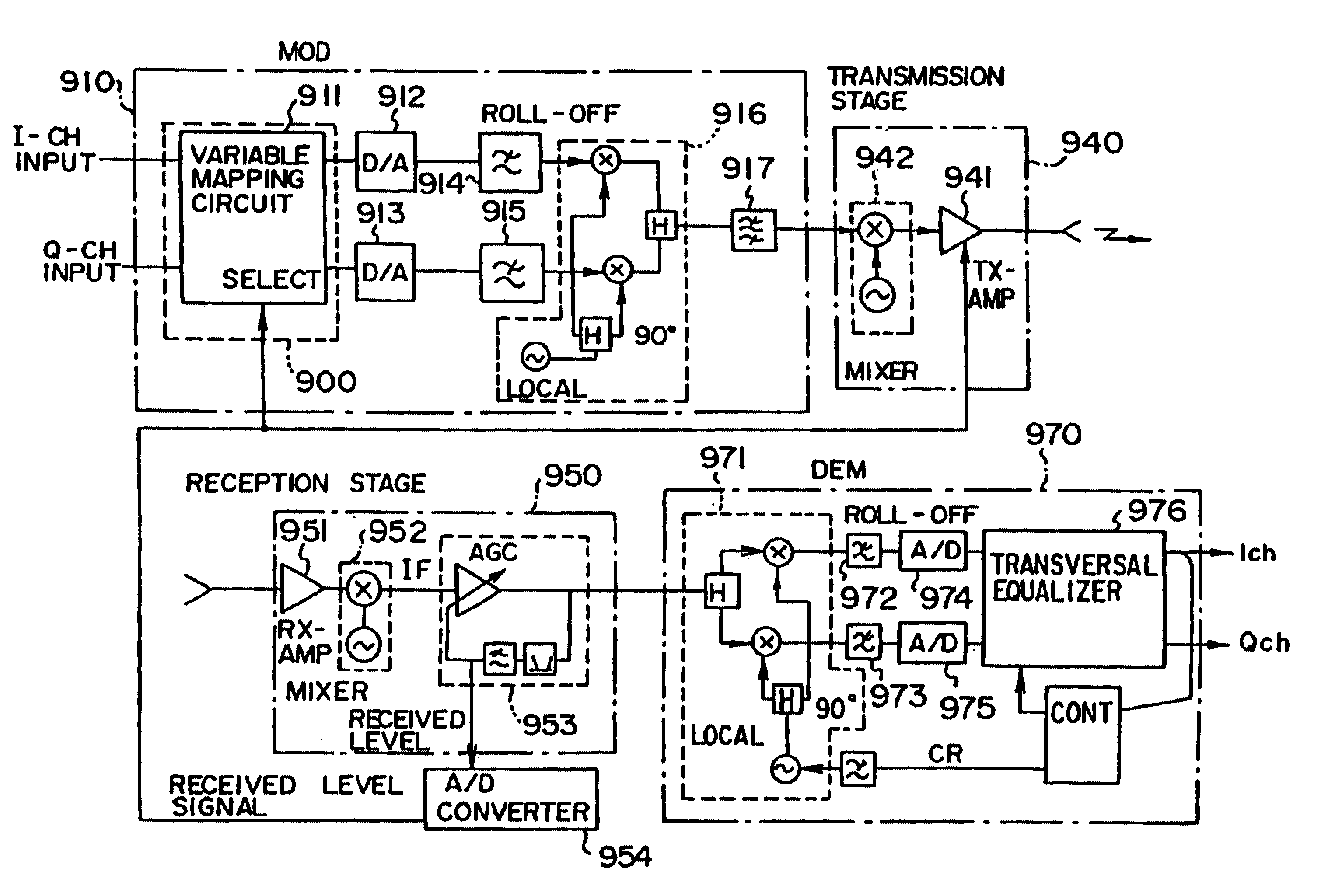
[0108]FIG. 24 shows a configuration of a distortion compensating system including the distortion compensating device according to the present invention. The distortion compensating system comprises a reception stage 840, a demodulator 830, and a distortion compensating device 800. The reception stage 840 includes an automatic gain controller (AGC) which can provide a received level of a digital signal to the distortion compensating device 800. The demodulator 830 may be the same as the demodulator 75 shown in FIG. 4. The distortion compensating device 800 comprises a plurality of discrimination circuits 8101 to 8103 and a selection circuit 820 for selecting one of the outputs of the discrimination circuits.
[0109]Each of the discrimination circuits 8101 to 8103 may have the same configuration as that of the discrimination circuit 710 shown in FIG. 22. However, the discrimination circuits 8101 to 8103, respectively, have different threshold patterns. For example, the threshold pattern...
PUM
 Abstract
Description
Claims
Application Information