Vertical shaft wind turbine with lifting power and resistance complementary adjustment

A vertical axis, wind turbine technology, applied in the direction of wind turbines at right angles to the wind direction, wind turbines, control of wind turbines, etc., can solve problems such as mechanical damage of fans, low wind speed, and generator output power decline, and achieve wind energy utilization The effect of increasing the wind speed, widening the wind speed range, and increasing the upper limit

Inactive Publication Date: 2011-08-03
NANJING YUNENG INSTRUMENT CO LTD
View PDF6 Cites 20 Cited by
  • Summary
  • Abstract
  • Description
  • Claims
  • Application Information

AI Technical Summary

Problems solved by technology

However, the fan structure in which the positions of the drag-type blades and the lift-type blades are fixed can reduce the wind speed required for fan startup, but it is still difficult to keep the rotation speed of the fan shaft at the rated speed under high wind speed conditions, because the lift type The linear speed of the blade can reach three to five times of the wind speed. If the rotating shaft speed of the fan exceeds the rated speed, it will cause mechanical damage to the fan on the one hand. Even if the mechanical structu...

Method used


Image

  • Vertical shaft wind turbine with lifting power and resistance complementary adjustment
  • Vertical shaft wind turbine with lifting power and resistance complementary adjustment
  • Vertical shaft wind turbine with lifting power and resistance complementary adjustment

Examples


Embodiment 1

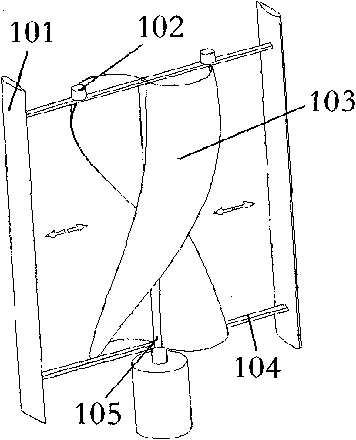
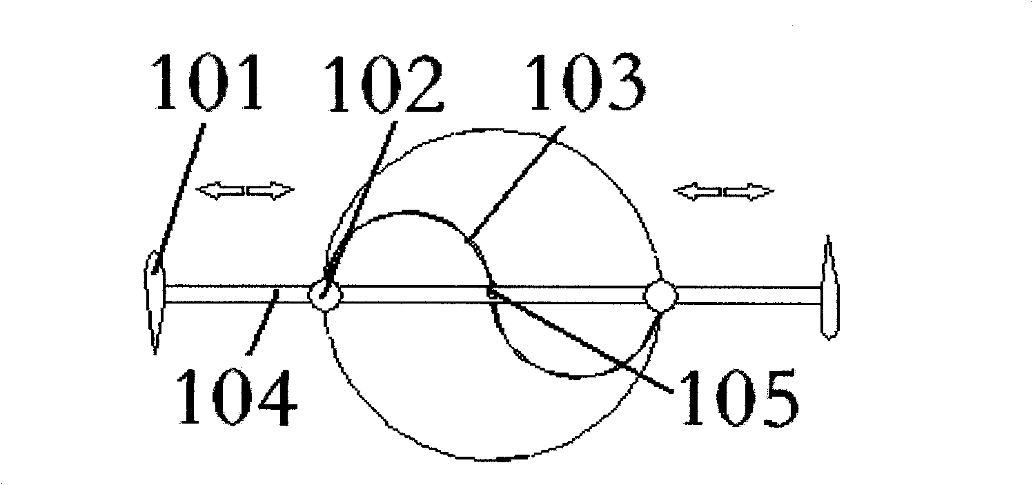
[0043] Embodiment 1 is an example of a vertical-axis wind turbine in which the helical drag-type blades and lift-type blades are complementary adjusted, and its structure is as attached figure 1 , 2 shown.

[0044] In this embodiment, the helical resistance blades 103 and the lift blades 101 are symmetrically distributed in pairs. The lift-type blade 101 is arranged on the outermost end of the beam 104 , and the resistance-type blade 103 can be displaced along the beam 104 between the rotating shaft 105 and the lift-type blade 101 , and its displacement power comes from the resistance-type blade displacement driving mechanism 102 . attached figure 1 , 2 The double-headed arrows in indicate that the resistance blade 103 can be displaced along the support beam 104 .

[0045] In the wind turbine of this embodiment, in order to obtain greater starting power under low wind speed conditions, the helical resistance blades 103 are displaced radially outward along the fan shaft 105...

Embodiment 2

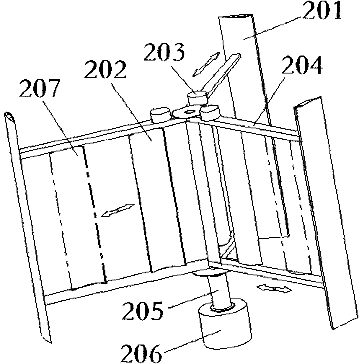
[0050] The second embodiment is an example of a vertical axis wind turbine in which the straight planar resistance blades and the lift blades are complementary adjusted, and its structure is as attached image 3 , 4 shown.

[0051] This embodiment is also a wind power engine in which lift-type blades and resistance-type blades are complementary and adjusted. The displacement between the lift-type blades 201 is powered by the resistance-type blade displacement drive mechanism 203 . attached Figure 9 , 10 The different positions of the drag vanes 207 are indicated by dotted lines in .

[0052] In the fan of this embodiment, under the condition of low wind speed, in order to obtain greater starting power, the resistance blades 202 are displaced radially outwards along the fan shaft. Inwardly displaced, so that within a relatively wide range of wind speeds, the lift-type blades rotate at a linear speed three to five times higher than the wind speed under the condition of low...

Embodiment 3

[0056] The three structures of this embodiment are as attached Figure 5 , 6 , 7, 8 shown.

[0057] This embodiment is also a wind power engine in which lift-type blades and resistance-type blades are complementary and adjusted. In this embodiment, the resistance-type blades 302 are in the shape of a straight plate. Between beams 304 and near the lift blade 301, the major axis of the resistance blade 302 is parallel to the fan shaft 305 and the major axis of the lift blade 301. Driven by the resistance blade angle drive mechanism 303, the resistance blade 302 can rotate around its long axis at any angle between zero and ninety degrees, thereby changing the size of its windward area.

[0058] In this embodiment, the fan in this embodiment is under the condition of low wind speed, in order to obtain a larger starting power for the fan, the resistance-type blades are in the largest windward area, that is, the resistance-type blades are parallel to the plane formed by the upper ...


PUM


Abstract

The invention relates to a vertical shaft wind turbine with lifting power and resistance complementary adjustment, which comprises a lifting power type vane, a resistance type vane, a support, a rotary shaft and a resistance type vane adjusting mechanism, wherein the adjusting mechanism is used for adjusting the position of the resistance type vane in the radical direction of the rotary shaft of the wind turbine or the windward side angle of the resistance type vane. By adjusting the position and the angle of the resistance type vane in the integral structure of the wind turbine, the optimal adjustment for the tip speed ratio Lambada of the vertical shaft wind turbine is simply and easily realized, the rated wind speed of the wind turbine can be designed or adjusted according to the actual wind speed and density of a wind field so that the wind turbine reaches the optimal wind energy collecting efficiency under a rated wind speed, the problem of low wind speed start of the wind turbine is solved, simultaneously the upper limit of wind energy and wind speed connection of the lifting power type vane is also improved, and the wind speed range of the wind turbine is further expanded so that the utilization rate of the wind energy is further improved; and besides, the damages and influences of super-high wind speeds (wind damages) to the wind turbine are also effectively reduced.

Description

technical field [0001] The invention relates to a wind power engine, in particular to a vertical axis wind power engine which is combined and adjustable with lift type blades and resistance type blades to realize complementary characteristics. Background technique [0002] Vertical-axis wind turbines and horizontal-axis wind turbines are two major categories of wind turbines today. Vertical-axis wind turbines do not need to face the wind when the wind direction changes, and can greatly simplify the structure of the fan. For a long time, they have attracted much attention and research. . [0003] The vertical axis wind turbine has experienced a long process of development and evolution, and there have been various forms of fan blades, and the lift type blade is the most commonly used one among various types of blades. However, there are two deficiencies in the vertical-axis wind turbine composed of a single lift-type blade. One is that it is difficult to start under low wind...

Claims


Application Information

Patent Timeline
IPC IPC(8): F03D3/00F03D3/06F03D7/06
CPCY02E10/74
Inventor 胡国祥李开平金厚铭王涛马振禄
Owner NANJING YUNENG INSTRUMENT CO LTD
Why Eureka
Try Eureka