Multi-stage backward gear speed changer with slide shaft roller keylock

A technology for reverse gears and sliding shafts, applied in gear transmissions, belts/chains/gears, instruments, etc., can solve problems such as large friction, and achieve the effects of small friction, light weight, and simple structure

Inactive Publication Date: 2011-08-03
KUNMING UNIV OF SCI & TECH
View PDF4 Cites 6 Cited by
  • Summary
  • Abstract
  • Description
  • Claims
  • Application Information

AI Technical Summary

Problems solved by technology

Relative to the rolling friction, the friction force is high, in addition, there are too few reverse gears, these disadvantages need to be avoided

Method used


Image

  • Multi-stage backward gear speed changer with slide shaft roller keylock
  • Multi-stage backward gear speed changer with slide shaft roller keylock
  • Multi-stage backward gear speed changer with slide shaft roller keylock

Examples


Embodiment Construction

[0024] Attached below figure 1 , 2 , 3, 4, 5, 6, 7, 8 and Examples further illustrate the present invention.

[0025] The technical problem to be solved by the present invention is to provide a sliding shaft roller key lock multi-stage reverse gear transmission, which can replace the existing stepped transmission. It has the advantages of simple structure, low cost and reliable use; less gear components, light weight and small volume; multi-stage reverse gear speed regulation, etc.

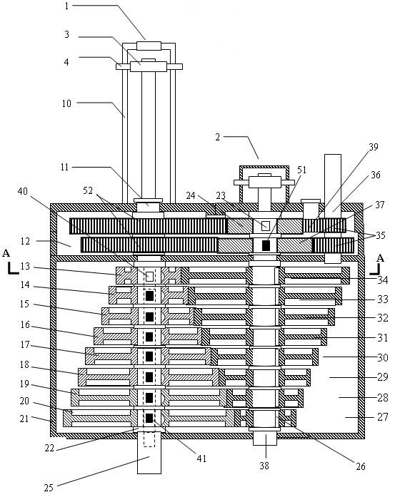
[0026] Adopt the embodiment of the present invention to be: speed changer is made of final reduction mechanism, transmission gear, power take-off shaft, speed change gear, speed control ring, gear position speed control device, gear position state determining device, speed changer casing etc.

[0027] Basic structure: the engine inputs power to the power input shaft 36 through the clutch, and the two main transmission gears 35 mesh with the main reduction gear 37 and the reverse gear 24 respecti...


PUM


Abstract

The invention relates to a multi-stage backward gear speed changer with a slide shaft roller keylock, which mainly comprises a main speed reducing mechanism, a transmission gear shaft, a transmission gear, a speed changing gear, a gear isolating ring, a power output shaft, a roller keylock device, a speed-regulating ring, a gear state determining device and a gear speed-regulating device. The multi-stage backward gear speed changer is provided with a gear state and a gear position. After power is inputted to a power input shaft, the gear state of the power input shaft is determined, and then primary speed reduction is carried out. All transmission gears on the transmission gear shaft are meshed with corresponding speed-changing gears. When the roller keylock is in a non-locked state, the speed-changing gears freely rotate relative to a power output shaft, and the roller keylock is in a neutral state. During speed regulation, a keylock slide shaft is pulled by a gear pull fork, the speed-changing gear locked in one gear is selected by changing the position of the keylock so that the speed change is realized. During gear reversing, the keylock slide shaft is pulled by the gear pull fork to change the state of the gear, the backward gear is locked, a reverse torque is outputted, and the function of multi-stage gear reversing is realized. The multi-stage backward gear speed changer can be widely applied to the field of carrying tools.

Description

technical field [0001] The invention relates to a vehicle gear transmission, in particular to a sliding shaft key lock multi-stage reverse gear transmission, which belongs to the field of vehicles. Background technique [0002] Simple, cheap and reliable transmissions have always been the research direction of transmissions. The current structure of transmissions is relatively too complicated, which makes the cost of transmissions too high. How to solve and create the simplest and most reliable transmission device is an extremely important issue. In the patent "sliding key lock gear transmission" and "sliding shaft key lock gear transmission", a sliding structure is adopted, which is sliding friction. Relative to rolling friction, the frictional force is large, and in addition, there are too few reverse gears, and these disadvantages need to be avoided. Contents of the invention [0003] The technical problem to be solved by the present invention is to provide a slidin...

Claims


Application Information

Patent Timeline
IPC IPC(8): F16H3/083F16H59/02F16H63/32
Inventor 陈蜀乔陈雨彤
Owner KUNMING UNIV OF SCI & TECH
Why Eureka
Try Eureka