Ratchet-type tensioner

A tensioner, ratchet-type technology, applied in belt/chain/gear, mechanical equipment, transmission, etc., can solve problems such as increased noise, increased chain burden, increased number of components, and increased manufacturing costs, and reduced jitter sound, the effect of preventing backward displacement

Inactive Publication Date: 2011-08-03
TSUBAKIMOTO CHAIN CO
View PDF7 Cites 5 Cited by
  • Summary
  • Abstract
  • Description
  • Claims
  • Application Information

AI Technical Summary

Problems solved by technology

[0005] In the above-mentioned conventional tensioner 500, the plunger retreat prevention tooth surface of the meshing tooth 536 and the rack 538 is formed as a tooth surface at right angles to the advancing and retreating direction of the plunger 514. The movement of the plunger 514 in the backward direction due to excessive chain tension will be restricted, and there are problems such as the plunger 514 is melted, or the chain is kept running under excessive tension, which may increase the burden on the chain or increase the noise.
[0006] Therefore, a predetermined amount of backlash is set for the ratchet mechanism composed of the meshing teeth 536 and the rack 538 in accordance with the maximum value of the movement in the backward direction of the plunger 514 assumed to be caused by excessive chain tension. , but the greater the amount of backlash above, the less able it is to reduce the beating sound called chattering sound when the engine is started.
[0007] In addition, if an orifice mechanism or an oil reservoir mechanism is added, or the plunger urging spring 518 is replaced in response to a high load, not only the number of parts and manufacturing cost will increase, but also the tensioner itself will be enlarged, and the orifice mechanism or The oil reservoir mechanism corresponds to the movement of the plunger 514 in the backward direction due to excessive chain tension due to the temperature change of the engine

Method used


Image

  • Ratchet-type tensioner
  • Ratchet-type tensioner
  • Ratchet-type tensioner

Examples


Embodiment Construction

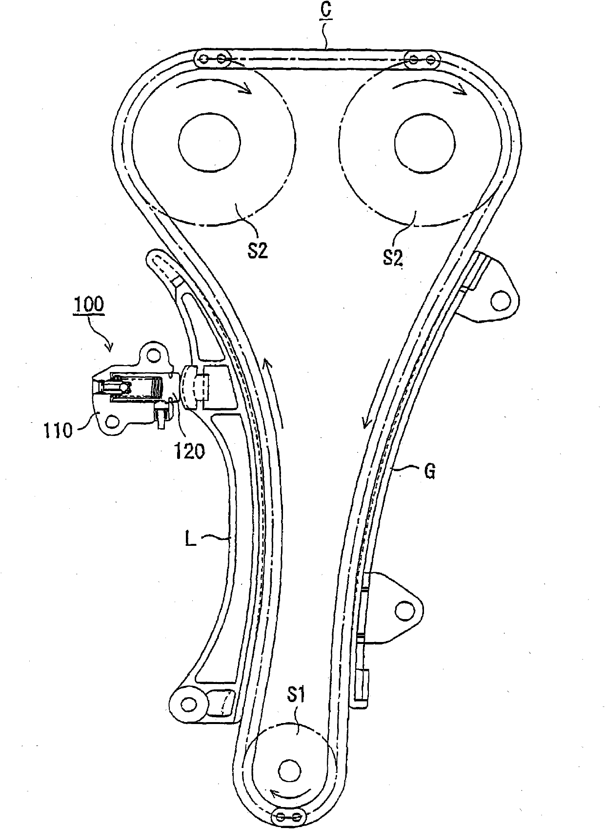
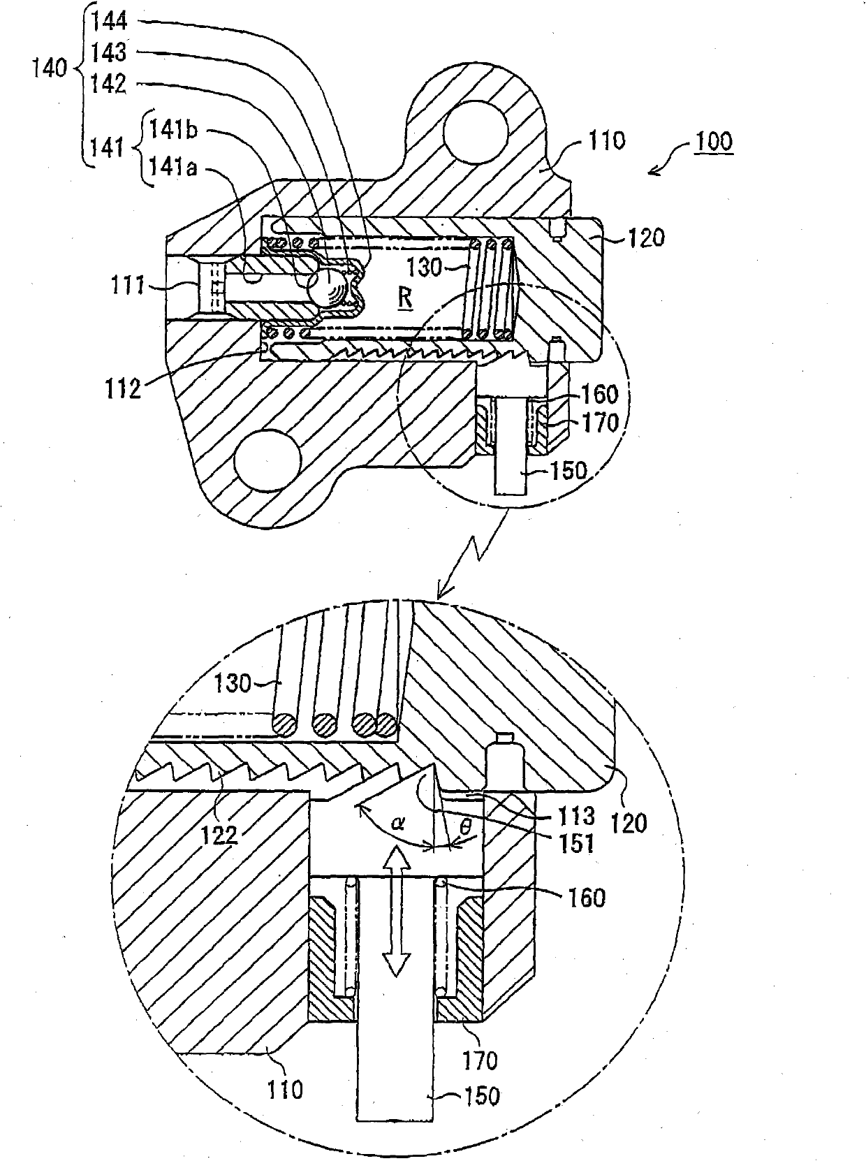
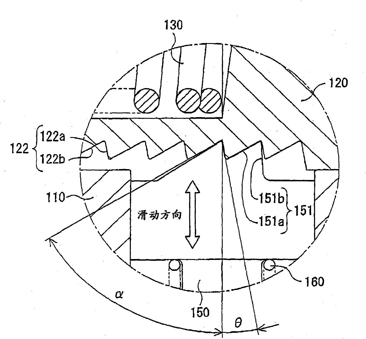
[0081] The ratchet type tensioner of the present invention includes: a casing body formed with an oil supply path for introducing external pressure oil; a plunger protruding from a plunger receiving hole of the casing body toward a traveling chain in a slidable manner. The spring for urging the plunger is accommodated in the high-pressure oil chamber formed between the plunger receiving hole of the housing body and the hollow part of the plunger, and urges the plunger in a direction to protrude; the check valve unit, It is put into the bottom of the above-mentioned plunger housing hole to prevent the pressure oil from flowing backward from the high-pressure oil chamber to the oil supply circuit; the piston with ratchet is embedded in the piston housing hole with ratchet of the above-mentioned housing body, and is connected with the plunger Sliding in the direction orthogonal to the advancing and retreating direction; the spring for applying force to the ratchet, which applies f...


PUM


Abstract

The present invention provides a ratchet-type tensioner, capable of preventing dithering sound from reducing due to backlash of a plunger to a timing chain when an engine is started after being placed for a long time, and not limiting action of the plunger in a back direction due to excess chain strain after starting the engine so as to prevent the plunger from fusion. In the ratchet-type tensioner (100), a force (Fs) of a spring (160) for a ratchet to applied to a toothed ratchet (122) on a side face of the plunger by a piston (150) which has a ratchet and slides in a direction transverse to the direction of plunger movement, is configured to be greater than a component (f1) of forces generated by a reaction force (F1) in a sliding direction of the piston (150) when the engine is started, and is configured to be less than a component (f2) of forces generated due to excess chain strain in the sliding direction of the piston (150) after the engine is started.

Description

technical field [0001] The present invention relates to a ratchet type tensioner for applying tension to a timing chain driving a camshaft or the like of an engine. Background technique [0002] Conventionally, there is known a tensioner which is used to drive a timing chain such as a camshaft of an engine, and applies a protruding force based on a spring and external oil pressure to be slidably inserted into a casing to form an oil chamber between the tensioner and the casing. on the plunger to provide tension to the timing chain. [0003] As such existing tensioners such as Figure 9 As shown, the following tensioner 500 is used, which has: a piston 526 that is slidably inserted in the housing 512 in a direction perpendicular to the sliding direction of the plunger 514 and forms a gap between it and the housing 512 Auxiliary oil chamber 520; make external oil pressure act on the oil passage 544 of auxiliary oil chamber 520; Air chamber 528, its built-in piston 526 applies...

Claims


Application Information

Patent Timeline
Patent Type & Authority Applications(China)
IPC IPC(8): F16H7/08
CPCF16H2007/0859F16H2007/0853F16H2007/0812F16H2007/0806F16H7/0848F16H7/08F16H7/18
Inventor 榑松勇二平山学
Owner TSUBAKIMOTO CHAIN CO
Why Eureka
Try Eureka