Light source device and backlight module with same

A technology of a light source device and a backlight module, which is applied to parts, light sources, electric light sources, etc. The effect of reducing the number

Inactive Publication Date: 2011-08-03
CHI LIN OPTOELECTRONICS CO LTD
View PDF5 Cites 27 Cited by
  • Summary
  • Abstract
  • Description
  • Claims
  • Application Information

AI Technical Summary

Problems solved by technology

figure 2 The middle part of the middle curve is extremely protruding, and there is a great drop between the two sides of the curve, which means that in the existing light-emitting diode 1 ( figure 1 ) within the entire light-emitting area, the middle area (between 11mm and 21mm) has extremely high brightness and the side areas (less than 11mm and greater than 21mm) have extremely small brightness, making the luminous brightness of each position extremely uneven
[0004] Depend on figure 1 and figure 2 The results show that the light of the existing light-emit

Method used


Image

  • Light source device and backlight module with same
  • Light source device and backlight module with same
  • Light source device and backlight module with same

Examples


Embodiment Construction

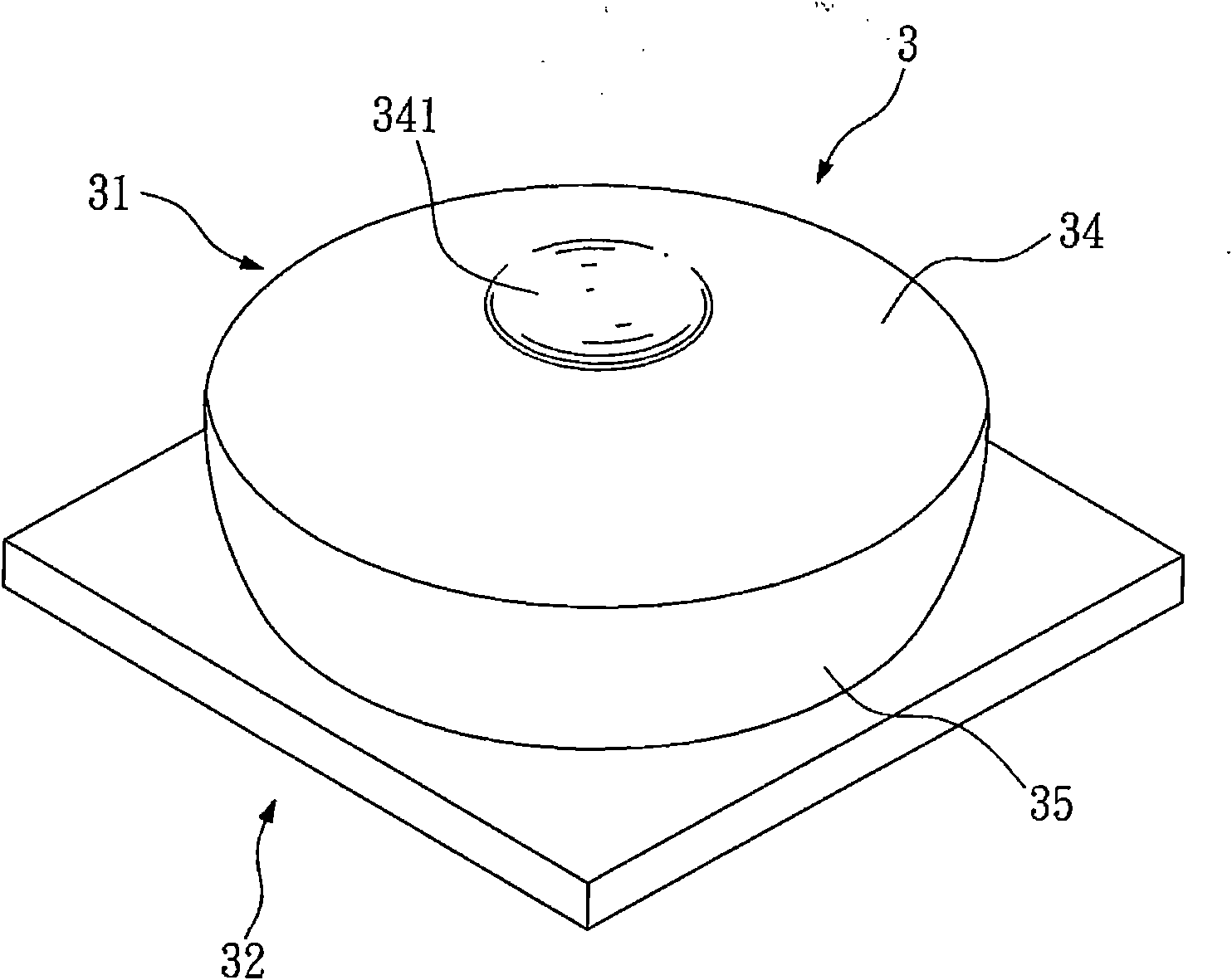
[0047] image 3 A perspective view showing the light source device of the present invention; Figure 4 A cross-sectional view of the light source device of the present invention is shown. with reference image 3 and Figure 4 , the light source device 3 includes a lens 31 and a light emitting diode 32 . Preferably, the material of the lens 31 can be polymethylmethacrylate (Polymethylmethacrylate, PMMA), but not limited thereto, any light-transmitting or light-guiding material can be applied to the material of the lens described in the present invention . The lens 31 has a bottom surface 33, an upper surface 34 and a side surface 35, the upper surface 34 is a diverging surface, the side surface 35 is a light-gathering surface, and the side surface 35 is adjacent to the bottom surface 33 and the upper surface 34, so as to In this embodiment, the side surface 35 is directly connected to the upper surface 33 . In addition, there may be a spacer surface (not shown) between th...


PUM

PropertyMeasurementUnit
Elevation angleaaaaaaaaaa

Abstract

The invention provides a light source device and a backlight module with the same. The light source device comprises a lens and a light emitting diode, wherein the lens is provided with a bottom surface, an upper surface and a lateral surface; the upper surface is a diffusion surface; the lateral surface is a light gathering surface; the lateral surface is adjacent to the bottom surface and the upper surface; and the light emitting diode is opposite to the lens. Therefore, the light source device can appropriately distribute light rays, so that the effect of uniformization in the range of a bright area of the backlight module of the light emitting diode can be achieved, and the number of optical membranes in the backlight module of the light emitting diode can be reduced.

Description

technical field [0001] The invention relates to a light source device and a backlight module including the light source device, in particular to a light source device with a lens and a backlight module including the light source device. Background technique [0002] refer to figure 1 , which shows a schematic diagram of distribution of existing light emitting diodes in an existing backlight module. In the existing backlight module 10, these existing light emitting diodes 1 are arranged in an array. respectively at position P 1 ,P 2 ,P 3 ,P 4 The brightness is measured at the relative position above, and the results are as follows, determined by the position P 1 The measured brightness is 12944nit; by the position P 2 The measured brightness is 10963nit; by the position P 3 The measured brightness is 11567nit; by the position P 4 The measured brightness is 11539nit. Among them, the maximum luminance values ​​measured at these positions (at position P 1 ) and the mi...

Claims


Application Information

Patent Timeline
IPC IPC(8): F21S8/00F21V5/04F21V5/00F21Y101/02F21Y105/16F21Y115/10
Inventor 李一昌
Owner CHI LIN OPTOELECTRONICS CO LTD
Why Eureka
Try Eureka