Heat pipe

A heat pipe, one-end technology is applied in the field of heat exchange equipment, which can solve problems such as affecting heat exchange efficiency, and achieve the effect of improving heat transfer efficiency and improving heat transfer efficiency.

Inactive Publication Date: 2011-08-03
JIANGXI ZHONGGUANG LIGHTING TECH
View PDF5 Cites 14 Cited by
  • Summary
  • Abstract
  • Description
  • Claims
  • Application Information

AI Technical Summary

Problems solved by technology

However, since the steam channel and the return channel are respectively communicated with the evaporating part and the condensing part, part of the liquid must be vaporized in the return channel and flow back to the condensing part along the return channel, and there must be some liquid in the steam channel. After the gas is condensed, it flows reversely along the steam channel to the evaporation part, which obviously affects the heat exchange efficiency

Method used


Image

  • Heat pipe
  • Heat pipe
  • Heat pipe

Examples


Embodiment 1

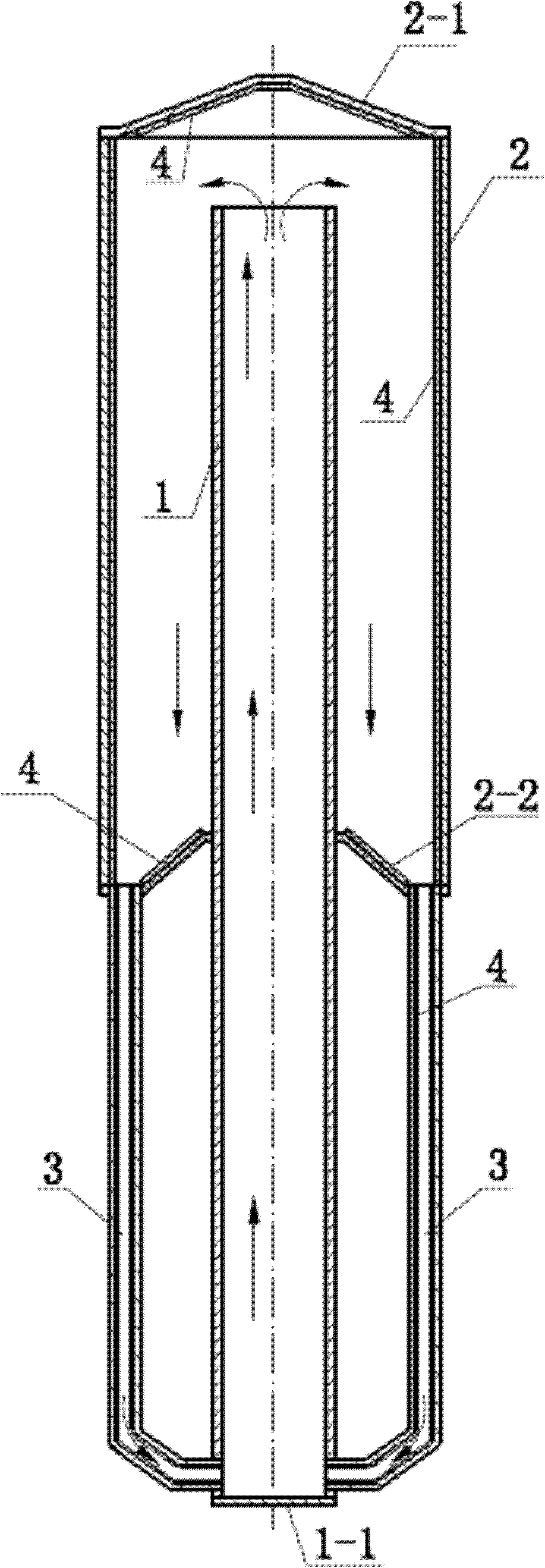
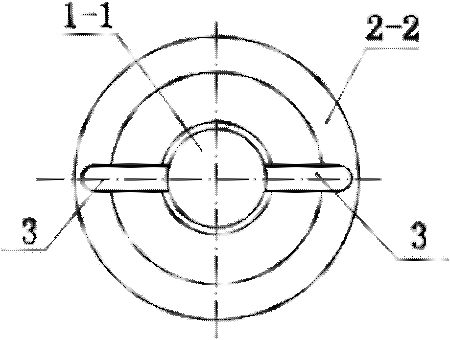
[0016] see Figure 1 to Figure 4 , the inner tube 1 is a cylindrical straight tube, the upper end of which is open, and the lower end is closed by the thermal end cap 1-1. The outer tube 2 is also a cylindrical straight tube, the closed end of the upper end is a conical condensation end cap 2-1, and the lower end is open. The inner tube 1 is coaxially inserted into the outer tube 2 , its open end extends to close to the condensation end cap 2 - 1 of the outer tube 2 , and the other end extends out of the outer tube 2 . The above-mentioned outer pipe 2 forms the condensation section of the heat pipe, and the part of the inner pipe 1 protruding from the outer pipe 2 forms the condensation section of the heat pipe. The open end of the outer tube 2 is provided with a sealing ring 2-2 which closes the annular opening between the outer tube 2 and the inner tube 1. The middle part of the sealing ring 2-2 is conical, and the upper and lower parts are radially inward and downward resp...

Embodiment 2

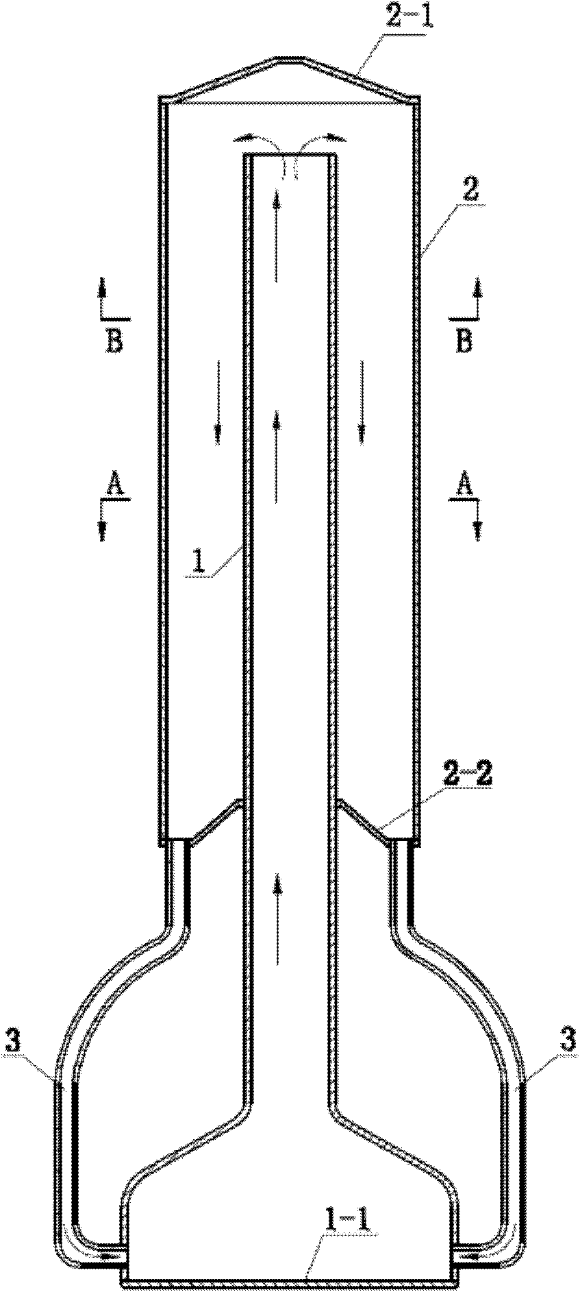
[0020] see Figure 3 ~ Figure 6 , the inner tube 1 of this embodiment radially expands into a convex shape at one end close to the closure, so that the area of ​​the closed end of the inner tube 1 increases. When in use, the end surface is close to the heat source, which is suitable for occasions where the heat source is distributed in a planar form, such as a computer CPU cooling. The inner wall of the outer pipe 2 and the return pipe 3 and the lower surface of the condensation end cover 2-1 and the upper surface of the sealing ring 2-2 are all provided with a capillary liquid-absorbing core 4, and the capillary liquid-absorbing core 4 is provided on the outer pipe 2. And the inner wall of the return pipe 3, the lower surface of the condensation end cover 2-1 and the upper surface of the sealing ring 2-2 are provided with a micro-groove structure 5 coated with a layer of hydrophilic material on the surface. Four return pipes 3 are evenly distributed on the sealing ring 2-2, ...


PUM


Abstract

The invention discloses a heat pipe which is characterized in that the heat pipe comprises an inner pipe (1) and an outer pipe (2), wherein one head of the inner pipe is closed, the other head of the inner pipe is opened, one head of the outer pipe (2) is closed, and the other head of the outer pipe (2) is opened; the opened head of the inner pipe (1) is inserted into the opened head of the outer pipe (2) along an axis and extends near the closed head of the outer pipe (2); a sealing ring (2-2) is arranged at the opened port of the outer pipe (2) and seals an annular opening between the outer pipe (2) and the inner pipe (1); a plurality of return pipes (3) made of a heat-insulating material uniformly pass through the sealing ring (2-2), respectively extend near the closed head of the inner pipe (1) and are respectively communicated with the inner pipe (1); and the outer pipe (2) is a condensing segment of the heat pipe, and a part of the inner pipe (1) arranged at the outside of the outer pipe (2) is an evaporation segment of the heat pipe. A vapor stream and a liquid stream in the heat pipe described by the invention are not mutually influenced, and the heat transfer efficiency is high.

Description

technical field [0001] The invention relates to a heat exchange device with an intermediate heat transfer medium in a closed pipe leading into or passing through the channel wall, in particular to a heat pipe. Background technique [0002] The heat pipe is a heat transfer element with extremely high thermal conductivity, which quickly transfers the heat of the heating object to the outside of the heat source through the evaporation and condensation of the liquid in the fully enclosed vacuum tube. Due to the advantages of high heat transfer efficiency and compact structure, heat pipes have been widely used in various heat dissipation occasions, solved the noise problem of traditional air-cooled heat dissipation, and opened up a new direction in the field of heat dissipation. [0003] A common heat pipe is a closed pipe body, one end of the pipe body is the evaporation end connected to the heat source, the other end is the cooling end, and a working medium is arranged in the p...

Claims


Application Information

Patent Timeline
Patent Type & Authority Applications(China)
IPC IPC(8): F28D15/02F28D15/04
CPCF28D15/025
Inventor 江帆
Owner JIANGXI ZHONGGUANG LIGHTING TECH
Why Eureka
Try Eureka