
Light guide plate and light-emitting diode (LED) lamp containing same

A technology of LED lamps and light guide plates, applied in the directions of optics, light guides, light sources, etc., can solve the problems of difficult control of light uniformity, low light utilization rate, low light utilization rate, etc., and achieve the effect of reducing the glare phenomenon

Active Publication Date: 2011-08-03
汉摩尼(江苏)光电科技有限公司
View PDF5 Cites 7 Cited by
  • Summary
  • Abstract
  • Description
  • Claims
  • Application Information

AI Technical Summary

Problems solved by technology

[0004] The process of direct-lit LED lamps is simple, and usually does not require a light guide plate. The LED array is placed at the bottom of the lamp, and the light emitted from the LEDs is emitted through the lampshade or directly. illumination
In addition, the thickness of the direct-type LED light source is determined by the distance between the bottom of the lamp and the diffuser plate. Generally, the thicker the thickness, the better the light uniformity of the LED light source, but the light utilization rate is reduced, so the product is more bulky, and the energy consumption is high. More expensive, small thickness, poor light uniformity, prone to dizziness, difficult to use for lighting
[0005] The advantage of side-lit LED lamps is that it can realize surface light source and emit light evenly. However, due to the reflection principle of the light guide plate, the light is continuously reflected in the light guide plate. Usually, the light utilization is only 60% to 80%. On the other hand, Uniformity of light is more difficult to control
The uniformity of side-lit LED light source lighting mainly depends on the dot design on the light guide plate. The larger the size of the light guide plate, the more difficult it is to achieve uniformity, and the lower the light utilization rate

Method used


Image

  • Light guide plate and light-emitting diode (LED) lamp containing same
  • Light guide plate and light-emitting diode (LED) lamp containing same
  • Light guide plate and light-emitting diode (LED) lamp containing same

Examples


Embodiment Construction

[0035] The specific embodiments of the present invention will be described below mainly in conjunction with the accompanying drawings.

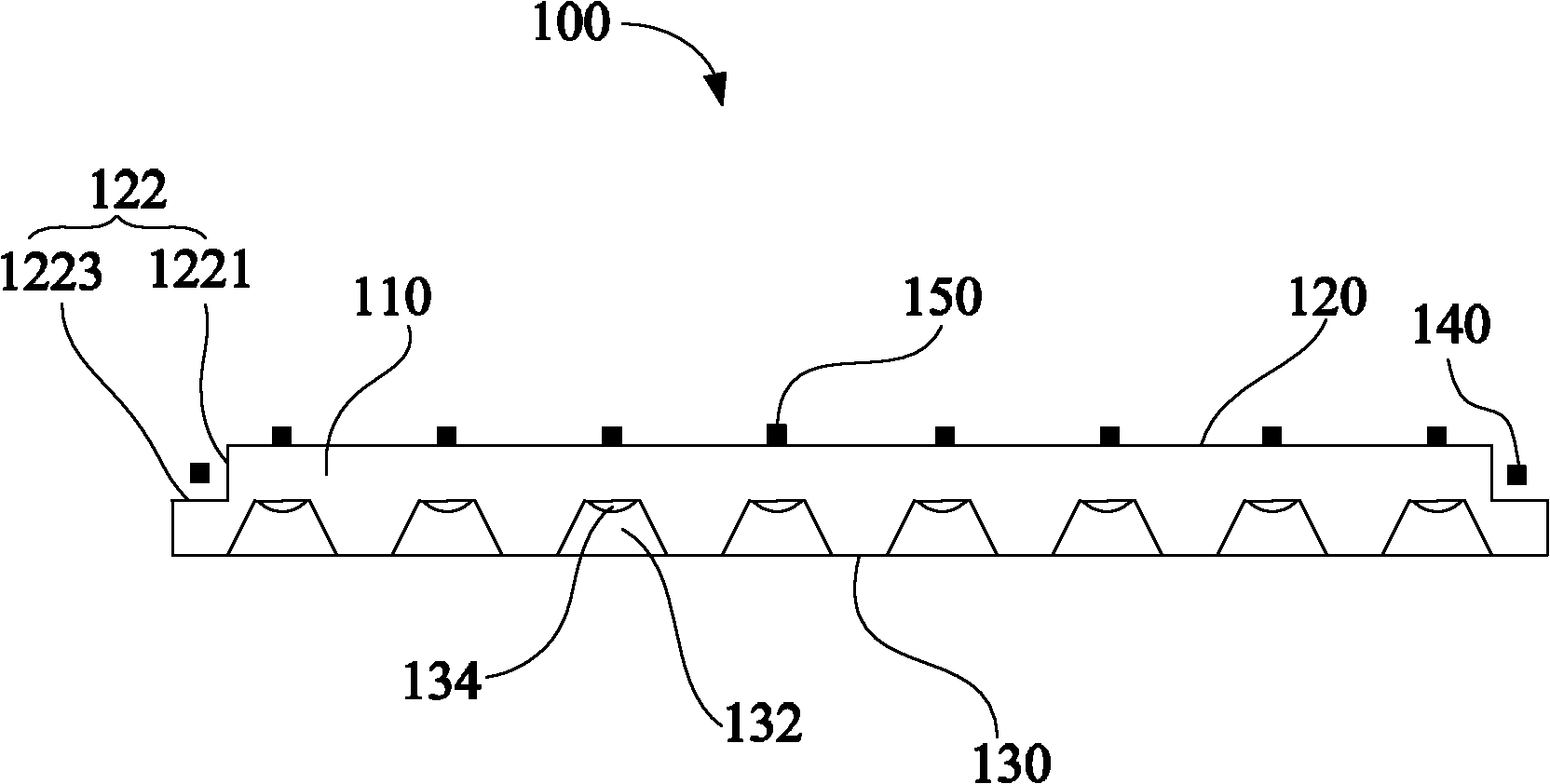
[0036] see figure 1 , the LED lamp 100 of Embodiment 1 includes a light guide plate 110 , a first LED light source 140 and a second LED light source 150 . The light guide plate 110 includes a transparent base (not shown), a light incident surface 120 and a light exit surface 130 .

[0037] In this embodiment, the transparent substrate is roughly rectangular, and it can be formed of a transparent resin material, for example, one or a combination of acrylic resin, polycarbonate resin, polystyrene resin and styrene-methyl methacrylate resin .

[0038] The light incident surface 120 is formed on the transparent base. The light incident surface 120 is substantially rectangular, and two sides thereof are formed with stepped portions 122 for accommodating the light source. The stepped portion 122 includes a first stepped surface 1221 and a secon...


PUM


Abstract

The invention relates to a light guide plate which comprises a transparent substrate, an incident surface and an emergent surface. The incident surface is formed on the transparent substrate, a step part used for accommodating light sources is formed at the edge of the incident surface, the emergent surface is formed on the transparent substrate and is opposite to the incident surface, and a reversed-frustum groove and an arc bulge arranged at the bottom of the reversed-frustum groove are formed on the emergent surface. In the light guide plate, the edge of the incident surface is provided with the step part, the step part and the middle part of the incident surface can be simultaneously provided with the light sources to form an incident mode coexisting a side light mode with a straight light mode, so that the utilization ratio of the light sources is improved and more uniform emergent light brightness is achieved; moreover, the reversed-frustum groove and the arc bulge arranged at the bottom of the reversed-frustum groove are formed on the emergent surface, the reversed-frustum groove is used for diffusing light rays, and the arc bulge is used for gathering the light rays to make polychromatic light rays fully mixed and decrease a glaring phenomenon. The invention also provides a light-emitting diode (LED) lamp containing the light guide plate.

Description

【Technical field】 [0001] The invention relates to a lighting tool, in particular to a light guide plate and an LED lamp containing the light guide plate. 【Background technique】 [0002] Environmental protection and energy saving have become the main trend of various electronic product reforms. With its energy saving, environmental protection, long life and other characteristics, LED has been widely used in various indications, displays, architectural landscape lighting and other fields. However, for LED lamps, especially white LED lamps, the color rendering of LEDs is a technical bottleneck that restricts them from entering indoor lighting, especially reading lighting and medical lighting. Improving light utilization, reducing costs, and enhancing color rendering are the keys to LED lighting. [0003] For the form of LED lighting, there are mainly two lighting modes: direct lighting and side lighting. [0004] The process of direct-lit LED lamps is simple, and usually doe...

Claims


Application Information

Patent Timeline
Patent Type & Authority Applications(China)
IPC IPC(8): F21Y101/02F21V8/00F21V19/00F21S2/00G02B6/00F21K9/61F21Y115/10
Inventor 赵宇波焦丽华郭雅群郭艳玲
Owner 汉摩尼(江苏)光电科技有限公司
Learn More