Method, system and device for transmitting wavelength division multiplexing passive optical network

A passive optical network and wavelength division multiplexing technology, applied in the field of optical communication, can solve the problems of different ONUs, complex system structure, high operation and maintenance costs, and achieve the effects of reducing costs, ensuring transmission performance, and solving polarization problems.

Active Publication Date: 2011-08-03
HUAWEI TECH CO LTD
View PDF4 Cites 39 Cited by
  • Summary
  • Abstract
  • Description
  • Claims
  • Application Information

AI Technical Summary

Problems solved by technology

However, the use of colored optical modules in ONUs will lead to a series of colored problems, such as: the ONUs of different users are different and cannot be used universally; when operators issue ONUs to users, they need to know the port wavelength corresponding to each user’s AWG Business distribution and warehousing of the merchants have brought great difficulties
Therefore, the existing WDM-PON system has a complex structure and high operation and maintenance costs

Method used


Image

  • Method, system and device for transmitting wavelength division multiplexing passive optical network
  • Method, system and device for transmitting wavelength division multiplexing passive optical network
  • Method, system and device for transmitting wavelength division multiplexing passive optical network

Examples


Embodiment 1

[0033] First, an embodiment of the present invention provides a polarization-independent reflective modulator.

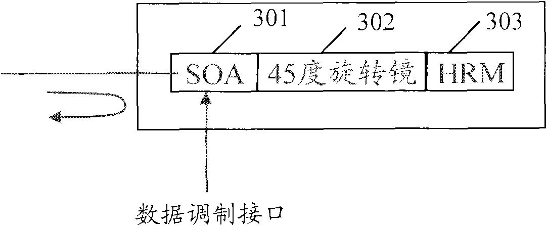
[0034] In the embodiment of the present invention, such as image 3 As shown, the polarization-independent reflective modulator 300 specifically includes: a semiconductor optical amplifier (SOA, Semiconductor Optical Amplifier) ​​301, a rotating mirror 302 and a mirror 303, wherein the semiconductor optical amplifier SOA 301 has a data modulation interface, that is, in addition to the amplification function In addition, it also has a modulation function. Wherein, the rotating mirror 302 can be a 45-degree rotating mirror, which can be used to rotate the polarization direction of the polarized light by a preset angle, such as 45 degrees. The mirror 303 may be a high reflection mirror (HRM, high reflection mirror).

[0035] The working principle of the reflection modulator can be found in Figure 4 . When the injected light passes through the polarization-dependen...

Embodiment 2

[0038] Embodiments of the present invention provide another polarization-independent reflective modulator. Such as Figure 5 Shown is a schematic structural diagram of the reflective modulator.

[0039] The reflective modulator 500 specifically includes: an SOA 501 and a Faraday Rotating Mirror (FRM, Faraday Reflection Mirror) 502 arranged along the optical path.

[0040] Among them, the Faraday rotating mirror 502 integrates the functions of the 45-degree rotating mirror 302 and the reflecting mirror 303, that is, the Faraday rotating mirror 502 can rotate the P light and S light of the output light of the SOA 501 after the first amplification by 90 degrees, Therefore, after the second amplification by the SOA 501 , the sum of the gain of the P light and the S light of the injection light injected into the SOA 501 is equal, and reflection modulation independent of the polarization of the injection light is realized.

Embodiment 3

[0042] An embodiment of the present invention provides an optical network unit, the optical network unit may include: at least one optical network unit transceiver module, the optical network unit transceiver module is used to receive downlink optical signals, and divide the downlink optical signals into There are two beams, one beam is used to obtain the downlink data loaded in the downlink optical signal after being demodulated, and the other beam is used as an uplink optical signal after polarization-independent amplification and modulation, and is used to carry the downlink data corresponding to the downlink data. upstream data.

[0043] In order to facilitate a further understanding of the present invention, the present invention will be described in detail below in conjunction with specific embodiments of the present invention. Such as Figure 6 As shown, the optical network unit transceiver module may include:

[0044] An optical splitter 601, configured to receive a ...


PUM


Abstract

The embodiment of the invention discloses a method for transmitting a wavelength division multiplexing passive optical network. The method comprises the following steps of: receiving a downlink optical signal from local terminal equipment, and dividing the downlink optical signal into a first optical signal and a second optical signal; demodulating the first optical signal so as to restore downlink data carried in the first optical signal; performing reflection irrelevant to polarization on the second optical signal so as to obtain a reflected light of which the polarization direction is orthogonal to the second optical signal, and loading uplink data to the reflected light corresponding to the second optical signal by a modulation method so as to generate an uplink optical signal carrying the uplink data; and transmitting the uplink optical signal to the local terminal equipment. By the embodiment of the invention, the decoloring of a light source can be realized, the cost is reduced effectively, and the transmission performance after reflection and modulation is guaranteed. The embodiment of the invention also discloses a system and a device for transmitting the wavelength division multiplexing passive optical network.

Description

technical field [0001] The present invention relates to the technical field of optical communication, and more specifically, relates to a transmission method, system and device of a passive optical network with wavelength division multiplexing. Background technique [0002] With the continuous increase of users' demand for bandwidth, the optical fiber access network has become a strong competitor of the next generation broadband access network, among which PON (Passive Optical Network, Passive Optical Network) is more competitive. figure 1 A general structure of an existing PON system is shown. Usually, the passive optical network system includes an OLT (Optical Line Terminal, Optical Line Terminal) located in the central office, an ODN (Optical Distribution Network, Optical Distribution Network) for branching / coupling or multiplexing / demultiplexing, and several ONU (Optical Network Unit, optical network unit). [0003] According to different PON implementations, PON can b...

Claims


Application Information

Patent Timeline
Patent Type & Authority Applications(China)
IPC IPC(8): H04Q11/00H04B10/14
Inventor 林华枫弗兰克・J・埃芬博格颜学进徐之光
Owner HUAWEI TECH CO LTD
Why Eureka
Try Eureka