Artificial respirator

A technology of artificial respiration and breathing parts, applied in the field of artificial respirators, can solve problems such as difficult to find, inconvenient to use, and no way to measure expiratory pressure

Inactive Publication Date: 2011-08-10
GALEMED (XIAMEN) CO LTD
View PDF6 Cites 8 Cited by
  • Summary
  • Abstract
  • Description
  • Claims
  • Application Information

AI Technical Summary

Problems solved by technology

[0004] When the patient needs to move due to changing the course of treatment or other factors, it is necessary to detach the connecting tube set 92 from the breathing mask 901 and make the breathing mask 901 stay on the patient's face, however, between the second pipe section 922 and the breathing mask 901 The tighter plug-in fit and the structural design of the second tube section 922 itself are difficult to find an appropriate force point, but it will make it difficult to separate the connecting tube set 92 from the breathing mask 901, and if the force applied during the removal process If it is too large, the breathing mask 901 will be pulled off from the patient's mouth and nose, so it is inconvenient to use
[0005] see figure 2 As shown, it is another structure of the breathing tube set 92', except that the breathing tube set 92' has a first tube section 921' for inserting into the recovery ball and a second tube section 922 for inserting into the breathing mask 'Besides, there is also a measuring device insertion port 93 arranged on the first pipe section 921', and the measuring device insertion port 93 can be used to insert a pressure measurement line or other pressure measurement devices to measure the The air supply pressure sent into the first tube section 921' by the recovery ball, however, the limitation of this breathing tube set 92' is that, due to the relationship of the one-way valve, there is no way to measure the disease using this breathing tube set 92'. The expiratory pressure exhaled from the breathing mask to the second tube section 922'
[0006] This shows that above-mentioned existing respirator obviously still has inconvenience and defect in structure and use, and urgently needs to be further improved
In order to solve the above-mentioned problems, the relevant manufacturers have tried their best to find a solution, but for a long time no suitable design has been developed, and the general product has no suitable structure to solve the above-mentioned problems. This is obviously the relevant industry. Urgent problem

Method used


Image

  • Artificial respirator
  • Artificial respirator
  • Artificial respirator

Examples


Embodiment Construction

[0029] For further elaborating the technical means and effects that the present invention takes to reach the intended invention purpose, below in conjunction with accompanying drawing and preferred embodiment, to its specific implementation, structure, feature and effect of the artificial respirator that proposes according to the present invention, Details are as follows.

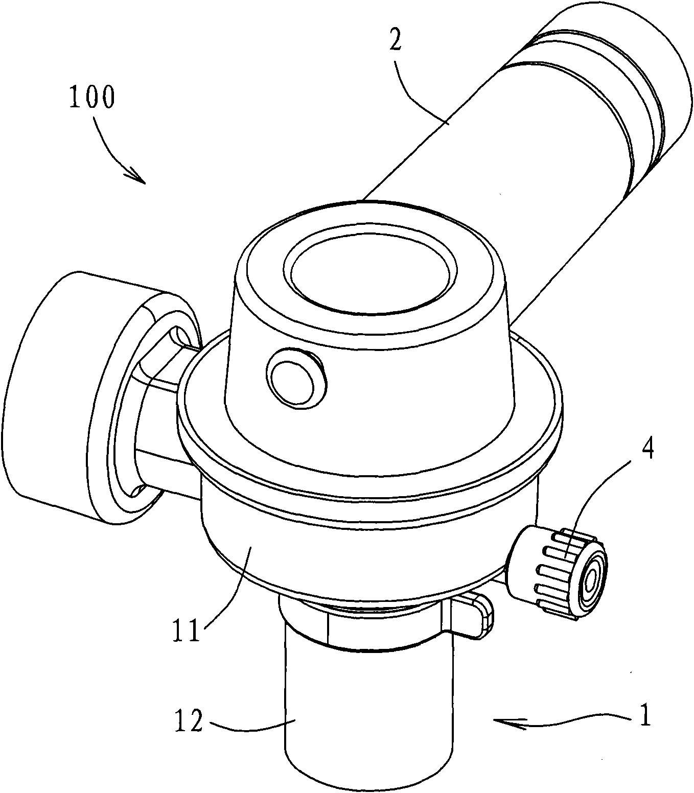
[0030] see Figure 3 to Figure 5 Shown are respectively a perspective view, a side view, and a longitudinal sectional view of another direction of the connecting tube set of a preferred embodiment of the connecting tube set of the artificial respirator of the present invention. The artificial respirator 10 of the preferred embodiment of the present invention is suitable for being connected to a breathing piece 7 to output gas to the patient's mouth and nose for inhalation. The artificial respirator 10 includes a flexible air bag 3 and a The tubing set 100 is connected.

[0031] In this example, image 3 ...


PUM


Abstract

The invention relates to an artificial respirator comprising an airbag with flexibility and a connecting tube set, wherein the airbag is of a hollow shape and is provided with an air delivering port; the airbag can be extruded to extrude the gas from the air delivering port; the connecting tube set is connected with the airbag and a respiration part such as a respiration mask; the gas extruded from the airbag enters the respiration part through the connecting tube set; the connecting tube set comprises a first tube part, a second tube part, a measuring device splicing port, a pressure relief valve port and a retaining wall which are connected with the airbag; the second tube part is connected with the first tube part and the respiration part and further is communicated with a first tube part and the respiration part; the measuring device splicing port and the pressure relief valve port are respectively formed at the second tube part; and the retaining wall is positioned in the second tube part and ensues that a gas flow path passing through the pressure relief valve port through the respiration part in the second tube part is not a linear path.

Description

technical field [0001] The invention relates to an artificial respirator, in particular to an artificial respirator which utilizes squeezing a wake-up ball to help patients breathe. Background technique [0002] In the past, patients who had difficulty breathing spontaneously relied on a mechanical ventilator to maintain ventilation in the hospital bed. Once they left the hospital bed, they needed to be manually ventilated with an artificial respirator with a recovery ball. [0003] see figure 1 As shown, the artificial respirator 9 (Resuscitator) that is generally plugged into the breathing mask 901 (or tracheostomy tube) is as figure 1 As shown, it includes a wake-up ball 91 and a connecting pipe set 92, the connecting pipe set 92 has a first pipe section 921 and a second pipe section 922 connected thereto, and a utility is provided between the first pipe section 921 and the second pipe section 922 A one-way valve to limit the one-way flow of gas from the first pipe sect...

Claims


Application Information

Patent Timeline
IPC IPC(8): A61M16/00
Inventor 李清昭
Owner GALEMED (XIAMEN) CO LTD
Why Eureka
Try Eureka