Die frame assembly

A technology for mold bases and backlight modules, which is applied in the field of mold bases, can solve problems such as the difficulty in reducing the size of male and female templates, the difficulty in reducing the cost of the mold base set 9, and the difficulty in reducing the cost of sliders, so as to reduce the size of the mold base, The effect of reducing injection molding power requirements and power consumption, reducing mold base materials and processing costs

Active Publication Date: 2011-08-10
SHINLONE INTELLIGENT MFG PRECISION APPL MATERIAL SUZHOU CO LTD
View PDF4 Cites 9 Cited by
  • Summary
  • Abstract
  • Description
  • Claims
  • Application Information

AI Technical Summary

Problems solved by technology

[0007] Due to the adoption of the above-mentioned mold opening / mold closing auxiliary parts 80, the existing mold frame group 9 also has such disadvantages: firstly, the structural design of the slider rear section 82 and the slider front section 81 makes the slider structure too large, not only It is difficult to reduce the cost of the slider, and because the template space it occupies is relatively large, it is difficult to reduce the size of the male and female templates 95, 92, and it is even more difficult to reduce the cost of the corresponding entire formwork group 9; secondly, due to the above The mold opening / closing auxiliary parts 80 need to be assembled in the frames 920 and 940 of the mold base group 9, so this frame-type positioning method also has the problem of high processing accuracy as mentioned above

Method used


Image

  • Die frame assembly
  • Die frame assembly
  • Die frame assembly

Examples


Embodiment Construction

[0018] Embodiments of the present invention are described with reference to the accompanying drawings, which illustrate specific embodiments in which the present invention may be practiced. The directional terms mentioned in the present invention, such as "upper", "lower", "front", "rear", "left", "right", "side", etc., are only referring to the directions of the attached drawings . These directional terms are used to illustrate and understand the present invention, but not to limit the present invention. In the following embodiments, the same parts are denoted by the same symbols in different drawings.

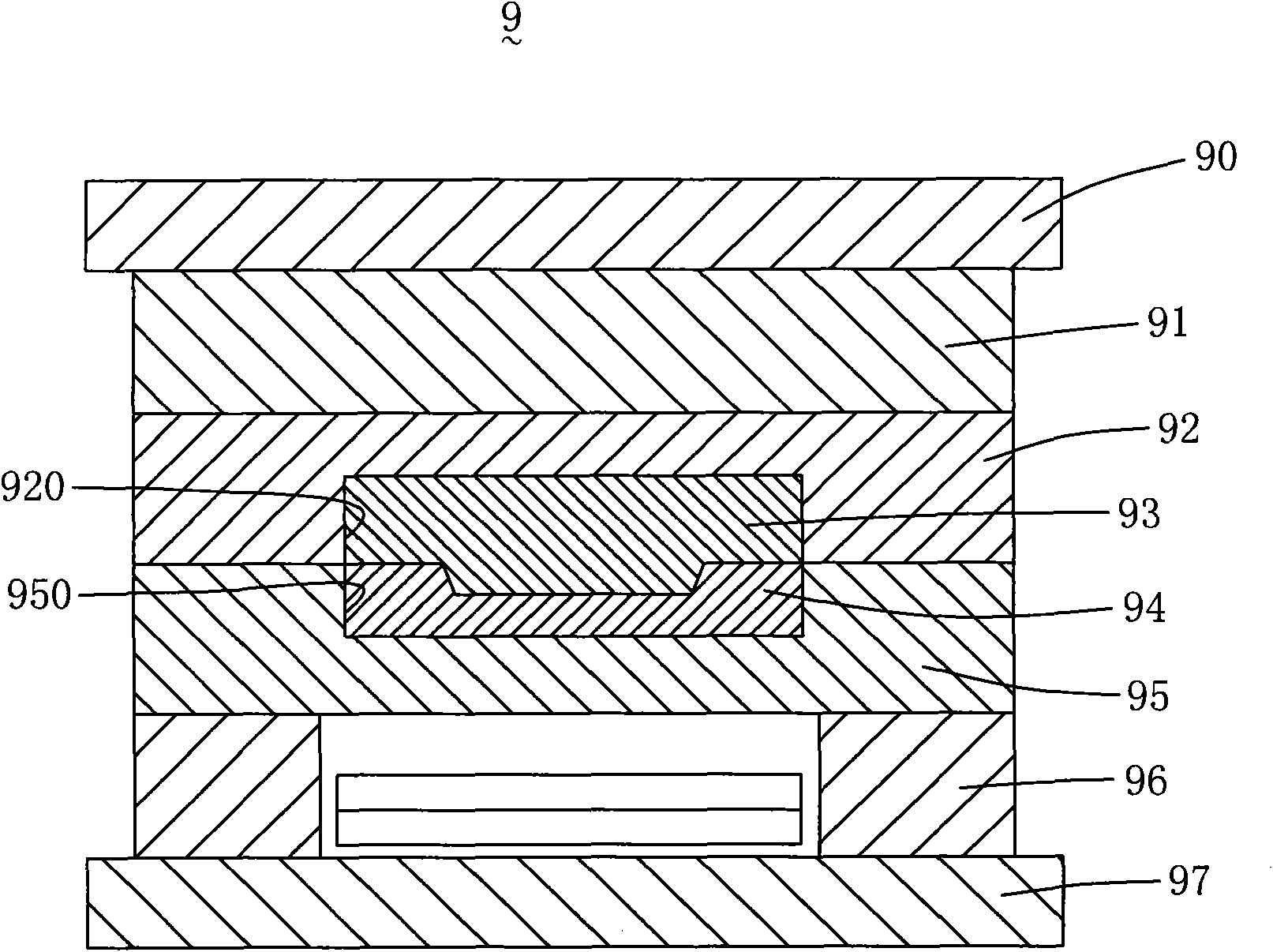
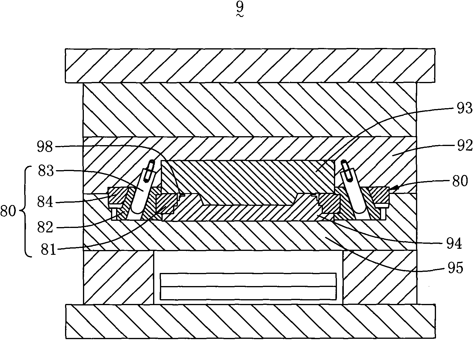
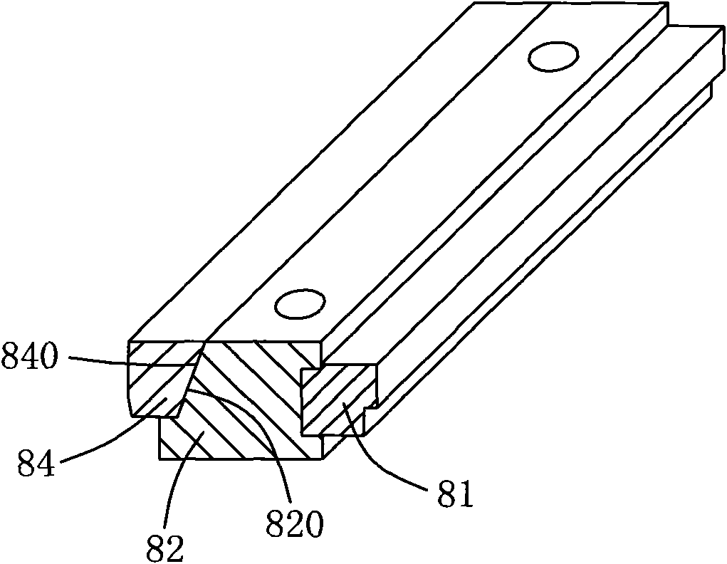
[0019] Please refer to Figure 4 to Figure 6 shown, where Figure 4 It is a schematic structural diagram of the mold base group 1 of the present invention; Figure 5 is in Figure 4 A schematic structural diagram of the mold base group 1 of the present invention provided with mold opening / mold closing auxiliary parts 40; and Figure 6 yes Figure 5 Shown is a schematic...


PUM


Abstract

The invention discloses a die frame assembly which comprises an upper fixing plate, a female die plate, a female die core, a male die core, a male die plate, a lower fixing plate and a die opening/closing auxiliary part. The male and female die cores are respectively fixed on the male and female die plates through supporting blocks. The die opening/closing auxiliary part comprises a sliding block, a support block, a binding block and an angle pin. The sliding block is horizontally connected with the support block side by side. The support block is arranged on the male die plate in a slideablemode and can drive the sliding block to slide on the male die plate. The binding block is fixedly arranged on the female die plate and is positioned above the support block. The angle pin is selectively arranged on one of the support block and the binding block and the other one of the support block and the binding block is provided with a chute. The angle pin can draw the support block in the process of closing a die so that the sliding block moves towards the male die core, and limits the support block to displace towards the direction far away from the male die core after the die is closed. By the die frame assembly, the size of a die frame can be effectively reduced so as to reduce the used material of the die frame and the machining cost, the assembling difficulty of the die also canbe greatly reduced and the correction of assembling the die is improved.

Description

【Technical field】 [0001] The present invention relates to a mold base set, in particular to a mold base set of a flat mold. 【Background technique】 [0002] Flat mold is an important tool for making large and medium-sized flat plastic parts. Since the cavity structure of flat mold and other injection molds is determined according to the structure of the product, once the product structure is determined, the corresponding mold process will also be determined. For plastic products, the mold technology has become increasingly mature, and the precision is getting higher and higher. Therefore, the key to the difference in mold technology in the future lies in the mold opening method. A good mold opening structure and mold opening method can reduce the difficulty of mold design and manufacture, and reduce the cost of mold processing. [0003] In addition, it takes a long time to develop a new set of plastic molds, which is also a major reason for extending the product development ...

Claims


Application Information

Patent Timeline
Patent Type & Authority Applications(China)
IPC IPC(8): B29C33/30B29C33/44B29C45/26
Inventor 郑景隆
Owner SHINLONE INTELLIGENT MFG PRECISION APPL MATERIAL SUZHOU CO LTD
Why Eureka
Try Eureka