Heat pipe and manufacturing method thereof

A heat pipe and pipe body technology, applied in the field of heat conduction, can solve the problems of low heat conduction efficiency of the heat pipe, and achieve the effects of increasing the volume, increasing the capillary force, and improving the return flow efficiency.

Inactive Publication Date: 2011-08-10
KUN SHAN DOTOP METAL TECH CO LTD
View PDF1 Cites 2 Cited by
  • Summary
  • Abstract
  • Description
  • Claims
  • Application Information

AI Technical Summary

Problems solved by technology

[0006] The present invention solves the problem of providing a heat pipe to improve the low heat conduction efficiency of heat pipes in the prior art

Method used


Image

  • Heat pipe and manufacturing method thereof
  • Heat pipe and manufacturing method thereof
  • Heat pipe and manufacturing method thereof

Examples


Embodiment Construction

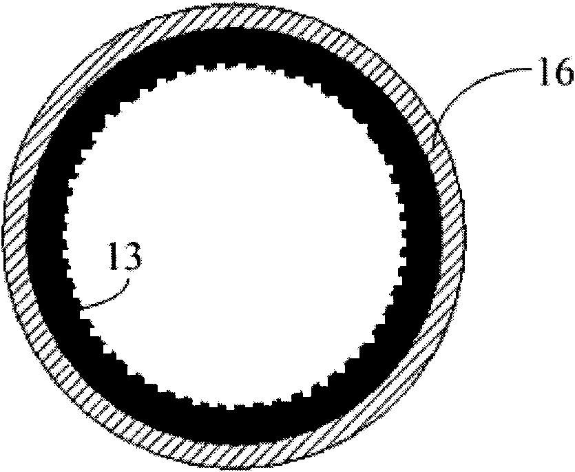
[0026] The designer found that for the capillary structure, the smaller the pores, the greater the capillary force generated by the capillary structure, and the larger the capillary force generated by the capillary structure, the larger the volume, the designer considered designing a heat pipe, which includes a larger The capillary structure with small volume and small pores can achieve high heat conduction efficiency.

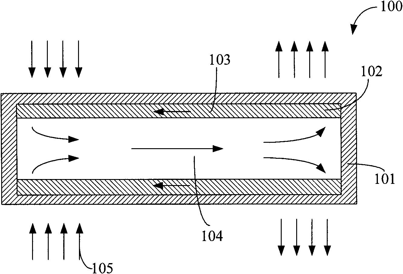
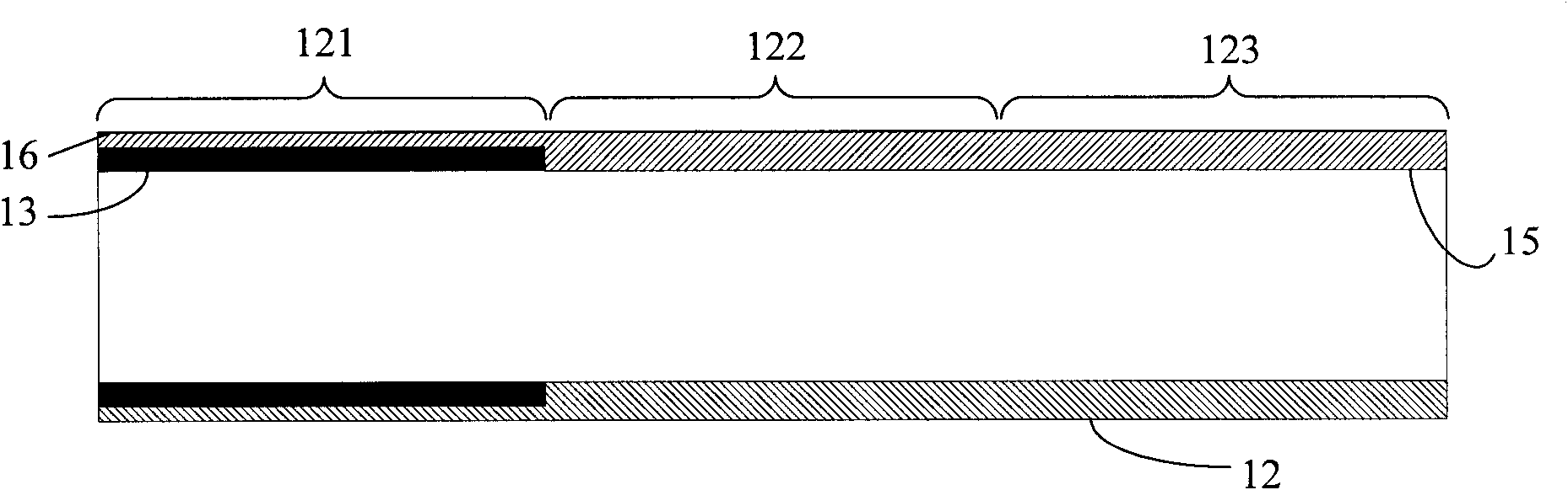
[0027] refer to figure 2 , shows a schematic diagram of an embodiment of the heat pipe of the present invention. The heat pipe includes: a tube body 12, the tube body 12 includes an evaporation part 121 and a condensation part 123 located at both ends of the tube body; a working medium filled in the tube body; and a working medium from the evaporation part to the condensation part. media channel.

[0028] The tube body 12 is a hollow cylindrical body, and the tube body 12 is usually made of a material with good thermal conductivity, such as metal materials ...


PUM

PropertyMeasurementUnit
thicknessaaaaaaaaaa
sizeaaaaaaaaaa

Abstract

The invention relates to a heat pipe which comprises a pipe body, wherein the pipe body comprises an evaporating part and a condensing part which are positioned at the two ends of the pipe body; the pipe body in the evaporating part region is provided with a smooth inner wall, and the smooth inner wall is covered with a master capillary structure; and the inner wall of the pipe body in the condensing part region forms an auxiliary capillary structure, and the capillary force of the auxiliary capillary structure is less than the capillary force of the master capillary structure. The method for manufacturing the heat pipe comprises the following steps of: providing the pipe body, wherein the pipe body comprises the inner wall with the auxiliary capillary structure; eliminating the auxiliary capillary structure at one end of the pipe body, and forming the smooth inner wall; providing a steel bar, and plugging one end of the steel bar with the auxiliary capillary structure into the pipe body to fill the pipe body with the auxiliary capillary structure; filling powder into the pipe body with the smooth inner wall; sintering the pipe body filled with the powder to form the master capillary structure; and extracting the steel bar.

Description

technical field [0001] The invention relates to the technical field of heat conduction, and in particular designs a heat pipe and a manufacturing method thereof. Background technique [0002] The heat pipe is a heat conduction component that relies on the phase change of the internal working medium to achieve heat dissipation. The heat pipe has the characteristics of high thermal conductivity and excellent isothermal property. In recent years, heat pipes have been widely used in electronic devices with large heat generation. [0003] A heat pipe is provided in Chinese patent ZL200320117731.1, refer to figure 1 , shows a schematic diagram of the heat pipe in said patent. The heat pipe 100 is composed of a pipe body 101 , a capillary structure 102 arranged on the pipe body 101 and a working medium (not shown) sealed in the heat pipe 100 . One end of the heat pipe 100 is an evaporating part, and the other end is a condensing part. The heat pipe 100 may further include an ins...

Claims


Application Information

Patent Timeline
Patent Type & Authority Applications(China)
IPC IPC(8): F28D15/04B23P15/26
Inventor 朱胜利
Owner KUN SHAN DOTOP METAL TECH CO LTD
Why Eureka
Try Eureka