Non-contact power supply device for rotating mechanism

A rotating mechanism, non-contact technology, applied in the direction of circuit devices, electrical components, electromagnetic wave systems, etc., can solve the problems of speed limitation, large energy loss, unsuitable for high-power, high-efficiency workplaces, etc., to achieve improved induction efficiency, Meet the effect of high power

Inactive Publication Date: 2011-08-10
TIANJIN UNIV
View PDF4 Cites 12 Cited by
  • Summary
  • Abstract
  • Description
  • Claims
  • Application Information

AI Technical Summary

Problems solved by technology

[0002] The traditional contact power supply method, such as the brush power supply method, has two major defects: one is that the slip ring is always in contact with the power supply brush, resulting in serious wear or damage, and the frequent replacement of the power supply brush cannot ensure stability and reliability. Second, in order to reduce the wear or damage of the slip ring, its speed is limited, so it cannot respond to the requirements of high-speed rotation
The above two non-contact power supply methods can be applied to non-contact power supply of other rotating mechanisms, but the induction efficiency is low, the energy loss is large, and it is not suitable for high-power and high-efficiency workplaces

Method used


Image

  • Non-contact power supply device for rotating mechanism
  • Non-contact power supply device for rotating mechanism
  • Non-contact power supply device for rotating mechanism

Examples


Embodiment Construction

[0034] The present invention will be further described in detail below in combination with specific embodiments.

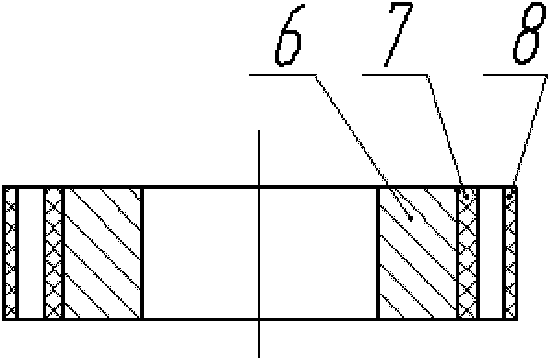
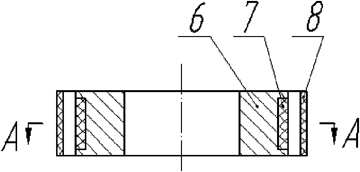
[0035] A non-contact power supply device for a rotating mechanism of the present invention includes a primary side and a secondary side, the primary side is composed of a primary side coil 8, and the secondary side is composed of a secondary side magnetic core 6 and a secondary side magnetic core The secondary side coil 7 on 6 constitutes; the secondary side is arranged at the center of the main side, and the main side and the secondary side are arranged on the same axis; in the radial direction, the inner diameter of the main side is approximately It is larger than the outer diameter of the secondary side, so that there is a gap between the two in the radial direction, and the gap should be minimized without affecting the rotation of the secondary side and the rotating mechanism.

[0036] The main side (fixed ring) is stationary, and the secondary side (moving ri...


PUM


Abstract

The invention discloses a non-contact power supply device for a rotating mechanism, which comprises a primary side and a secondary side. The primary side consists of a primary side coil, and the secondary side consists of a secondary side core and a secondary side coil wound on the secondary side core. The primary side coil is arranged statically relative to a base of the rotating mechanism. The secondary side core is fixedly arranged on a rotating body of the rotating mechanism, and rotates along with the rotating body. The primary side coil is connected with a power supply arranged outside the rotating mechanism, and electrical energy is transferred to the primary side coil of the non-contact power supply device. The primary side coil transfers the electrical energy to the secondary side coil of the non-contact power supply device in a non-contact way by electromagnetic induction. The secondary side coil of the non-contact power supply device is connected with a part required to be supplied with power on the rotating body of the rotating mechanism, and finally the electrical energy is transferred to the part required to be supplied with the power on the rotating body. The non-contact power supply device provided by the invention realizes the highly-efficient energy transfer of the non-contact power supply device of the rotating mechanism, reduces energy loss and avoids limitations to rotating speed.

Description

technical field [0001] The invention relates to a non-contact power supply device, in particular to a non-contact power supply device for a rotating mechanism. Background technique [0002] The traditional contact power supply method, such as the power supply method using brushes, has two major defects: first, the slip ring is always in contact with the power supply brush, resulting in serious wear or damage, and the frequent replacement of the power supply brush cannot ensure stability and reliability. Second, in order to reduce the wear or damage of the slip ring, its speed is limited, so it cannot respond to the requirements of high-speed rotation. [0003] The patent application number is 200680024192.3 (the publication number is CN101213042A), and the Chinese patent application published on July 2, 2008 discloses a "Spindle Device for Ultrasonic Machining", in which the non-contact power supply method using a single two-coil induction is The transducer of the rotating ...

Claims


Application Information

Patent Timeline
Patent Type & Authority Applications(China)
IPC IPC(8): H02J17/00H02J50/10
Inventor 林彬刘礼平朱学明
Owner TIANJIN UNIV
Why Eureka
Try Eureka