

Tool for minimally invasive surgery and method for using the same
A technology of minimally invasive surgery and tools, applied in the field of tools for minimally invasive surgery and its use, can solve the problems of inconvenient and complicated operation, and achieve easy movement, small volume and weight, exquisiteness and easy surgical operation Effect
- Summary
- Abstract
- Description
- Claims
- Application Information
AI Technical Summary
Problems solved by technology
Method used
Image

Examples
Embodiment 1
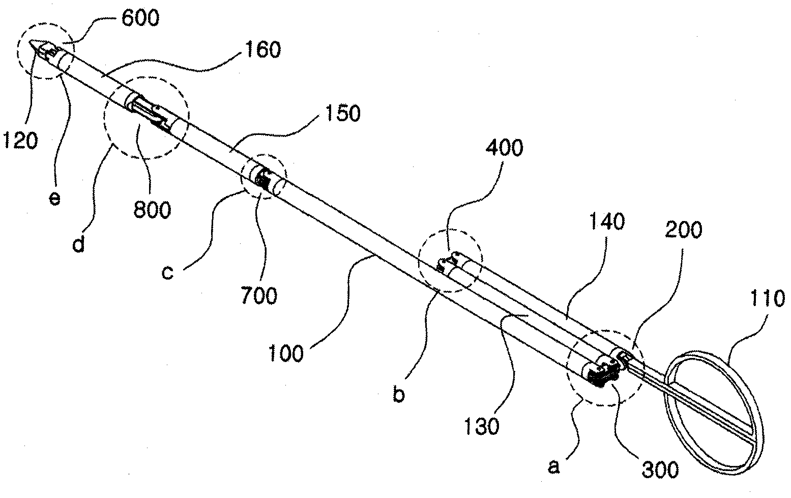
[0077]figure 1 is a perspective view showing the appearance of the tool 1 for minimally invasive surgery according to the first embodiment of the present invention.
[0078] refer to figure 1 , the tool 1 for minimally invasive surgery of the present embodiment includes a shaft 100 (ie, a main shaft), an adjustment handle 110, an end effector 120, a first control shaft 130 and a second control shaft 140, a first drive shaft 150 and The second drive shaft 160 , the pitch control part 200 , the first yaw control part 300 and the second yaw control part 400 , the pitch drive part 600 , and the first yaw drive part 700 and the second yaw drive part 800 .
[0079] First, if figure 1 As shown, there is a main shaft 100 , and a first control shaft 130 and a second control shaft 140 are sequentially located from one end of the main shaft 100 , and a first drive shaft 150 and a second drive shaft 160 are sequentially located from the other end of the main shaft 100 . At least a porti...
Embodiment 2
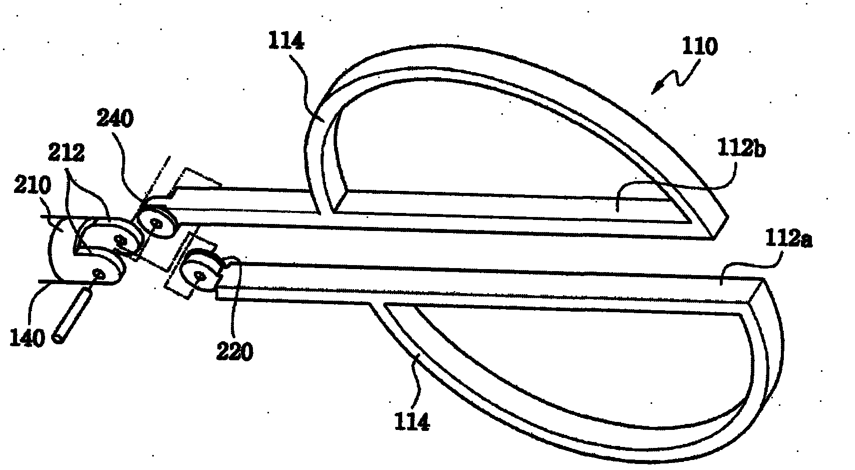
[0121] Figure 24 is a perspective view showing the connection between the adjustment handle 110 and the second control shaft 140 of the tool for minimally invasive surgery according to the second embodiment of the present invention. According to the second embodiment of the present invention, the adjustment handle 110 is connected to the second control shaft 140 through the pitch control part 200a.
[0122] More details on such structures are given below.
[0123] The pitch control part 200a may include a first pitch cable pulley 220a, a second pitch cable pulley 240a, and a third pitch cable pulley 260a. As shown in the drawing, among the first lever 112a and the second lever 112b constituting the adjustment handle 110, the first lever 112a has a first pitch cable pulley 220a fixed to its extended end and a first pitch cable pulley 220a positioned on the same rotation axis. The second pitch cable pulley 240 a to independently rotate inside the connection end 212 formed on ...
Embodiment 3
[0129] Figure 26 is a perspective view showing the appearance of a tool for minimally invasive surgery according to a third embodiment of the present invention, Figure 27 yes Figure 26 A detailed view of section 'b' in the , and Figure 28 yes Figure 26 A detailed view of section 'a' in .
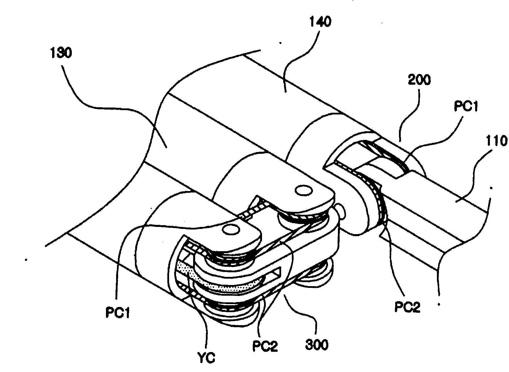
[0130] According to the third embodiment of the present invention, the adjustment handle 110a for controlling the operation of the end effector 120a in the form of a hook electrode is connected to the second control shaft 140 through the pitch control part 200, and the end effector 120a is connected to the second control shaft 140 through the pitch drive part. 600 is connected to the second drive shaft 160 .
[0131] In this embodiment, the first pitch cable PC1 and the second pitch cable PC2 operate together to transmit the motion of the adjustment handle 110a in the pitch / yaw direction to the end effector 120a.
[0132] In addition, unlike in the first embodiment, the end effecto...
PUM
 Abstract
Description
Claims
Application Information