Rope-driven joint module

A joint module and drive module technology, which is applied in the directions of manipulators, joints, program-controlled manipulators, etc., can solve the problems of failure to achieve modularization, uncompact structure, and insufficient use of rope drive, and achieve a simple and compact overall structure. Achieving dexterous, lightweight effects

Active Publication Date: 2021-03-09
GUANGDONG UNIV OF TECH
View PDF8 Cites 4 Cited by
  • Summary
  • Abstract
  • Description
  • Claims
  • Application Information

AI Technical Summary

Problems solved by technology

[0004] At present, there is a small amount of research on one-degree-of-freedom variable stiffness joints in China. For example, Chinese patent CN210998800U discloses a rope-driven joint, which can realize flexible cushioning. Compact and not modular, does not take full advantage of rope drives

Method used


Image

  • Rope-driven joint module
  • Rope-driven joint module
  • Rope-driven joint module

Examples


Embodiment 1

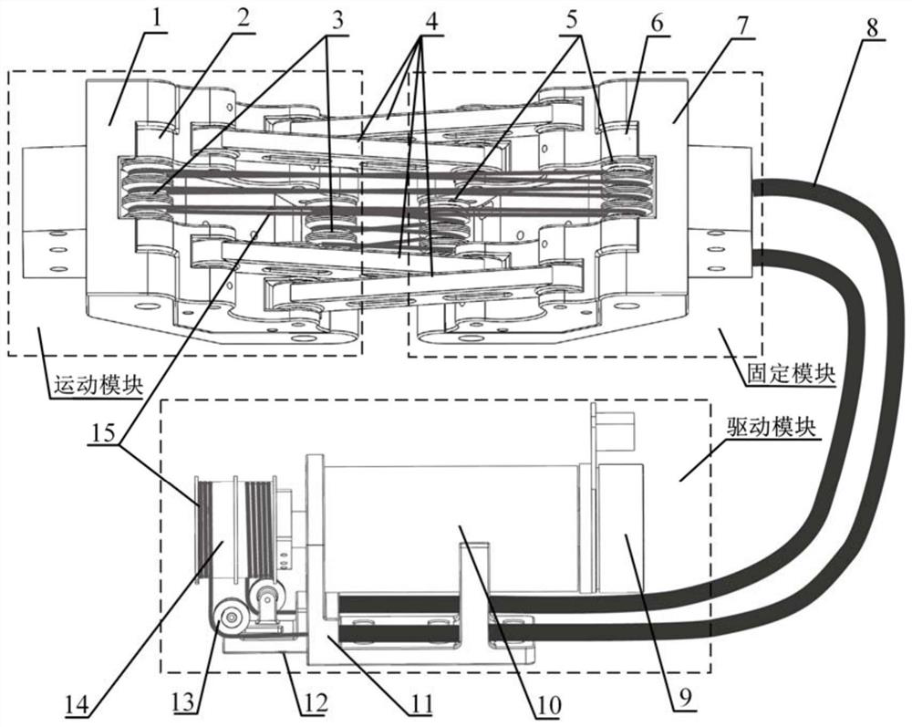
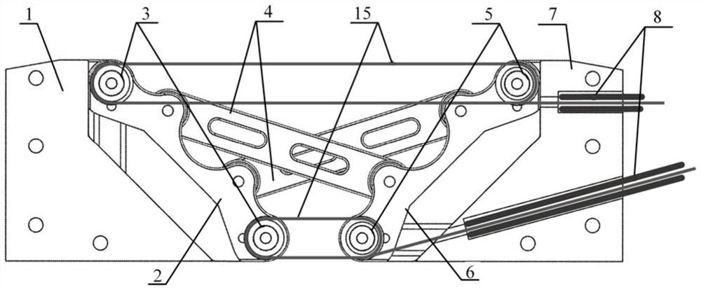
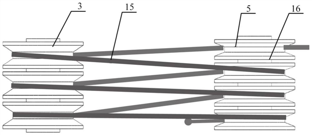
[0035] like Figure 1-3As shown, a kind of rope-driven joint module includes a motion module, a fixed module, a drive module, a connecting rod 4 and a rope 15; the motion module includes a motion base 2 and a movable pulley block movably connected thereto; the fixed module includes a fixed base 6 and The fixed pulley block that is movably connected with it; the two ends of the connecting rod 4 are respectively connected to the motion base 2 and the fixed base 6 in rotation, the movable pulley block is arranged on the motion base 2, and the fixed pulley block is arranged on the fixed base 6; the motion module and The fixed module is connected with the driving module through a rope 15 .

[0036] In the present invention, the fixed module and the moving module are connected through the connecting rod 4, the connecting rod 4 can swing around the fixed module and the moving module at the same time, the fixed module and the moving module can rotate around the connecting rod 4, and t...


PUM


Abstract

The invention relates to the technical field of robot joint design, in particular to a rope-driven joint module. The joint module comprises a moving module, a fixed module, a driving module, a connecting rod and a rope; the moving module comprises a moving base and a movable pulley block movably connected with the moving base; the fixed module comprises a fixed base and a fixed pulley block movably connected with the fixed base; the two ends of the connecting rod are rotationally connected with the moving base and the fixed base, the movable pulley block is arranged on the moving base, and thefixed pulley block is arranged on the fixed base; and the moving module and the fixing module are connected with the driving module through the rope. The rope-driven joint module is a one-degree-of-freedom rope-driven joint module which is high in rigidity, low in rotational inertia, small in size, light in weight and low in cost, and the safety and high efficiency of a bionic mechanical arm canbe effectively improved.

Description

technical field [0001] The invention relates to the technical field of robot joint design, in particular to a rope-driven joint module. Background technique [0002] With the rapid development of robot technology, robots are gradually applied to all walks of life, especially in large-scale production lines, where robots have basically replaced labor. With the continuous improvement of social productivity and the rapid development of the economy, people expect to apply robots to ordinary life, such as home care, education, greeting guests, etc., but traditional robots have problems such as large size, heavy weight, and low safety Its working environment is limited, and more dexterous, light, and safe robots are needed to make up for this defect. [0003] The rope drive technology is considered to be an important method to reduce the weight of the manipulator and improve the dexterity and safety of the manipulator. It is transmitted to the joint by the rope; 2) It can reduce...

Claims


Application Information

Patent Timeline
Patent Type & Authority Applications(China)
IPC IPC(8): B25J9/10B25J17/00
CPCB25J9/104B25J17/00
Inventor 张涛王斌王兵晁超越吴炳林管贻生
Owner GUANGDONG UNIV OF TECH
Why Eureka
Try Eureka