Modular saw chain type cutting box and using method thereof

A cutting box, modular technology, applied in the direction of earth mover/shovel, mechanically driven excavator/dredger, construction, etc., can solve the safety of connecting wall leakage, poor processing technology, and safety of foundation pit problems, to achieve the effect of good processing technology, convenient installation and operation, and flexible size changes.

Active Publication Date: 2019-02-15
CHINA CONSTR THIRD ENG BUREAU GRP CO LTD
View PDF5 Cites 1 Cited by
  • Summary
  • Abstract
  • Description
  • Claims
  • Application Information

AI Technical Summary

Problems solved by technology

[0002] At present, the grooves of reinforced concrete ground connecting walls are protected by artificial mud to ensure the stability of the groove walls. After the concrete is poured, even if a large amount of mud is recovered and processed for secondary treatment, a large amount of waste slurry will still be generated. If the waste slurry is directly disposed of Outward discharge is not conducive to green construction
The ground connection wall is generally used as the enclosure structure of the foundation pit and the water-stop system of the side wall. The traditional ground connection wall is designed in frames during construction. Seams often become frequent nodes of foundation pit leakage, resulting in potential safety hazards after foundation pit excavation
[0003] In order to solve the problem of construction mud pollution and the potential safety hazards caused by the leakage of the framing ground connection wall, the prior art has emerged a process of synchronously cutting and pouring the concrete floor connection wall, which can realize the cutting and drainage of the soil without a large amount of wall protection mud. Perfusion is performed synchronously
However, the cutting boxes used in the process of synchronously cutting and pouring concrete floor connecting walls are all integrated structures, and a single cutting box has the problems of large size, poor processing technology, high manufacturing cost, and inability to adapt to changes in various groove widths.
[0004] In addition, when using the process of synchronous cutting and pouring concrete ground connection wall, it is necessary to balance the earth pressure by cutting the side wall of the box to prevent the groove from collapsing. However, if the gap between the side wall of the cutting box and the groove wall is unreasonable or the friction resistance with the soil In this case, there will be a risk of the cutting box burying the drill, and because the cutting box is an integrated structure, the cutting box without a large amount of wall protection mud cannot be switched to a mud wall to ensure the stability of the groove wall

Method used


Image

  • Modular saw chain type cutting box and using method thereof
  • Modular saw chain type cutting box and using method thereof
  • Modular saw chain type cutting box and using method thereof

Examples


Embodiment Construction

[0030] In order to make the purpose, technical solutions and advantages of the embodiments of the present invention clearer, the technical solutions in the embodiments of the present invention will be clearly and completely described below in conjunction with the drawings in the embodiments of the present invention. Obviously, the described embodiments It is a part of embodiments of the present invention, but not all embodiments. It should be understood that the specific embodiments described here are only used to explain the present invention, not to limit the present invention. Based on the embodiments of the present invention, all other embodiments obtained by persons of ordinary skill in the art without making creative efforts belong to the protection scope of the present invention.

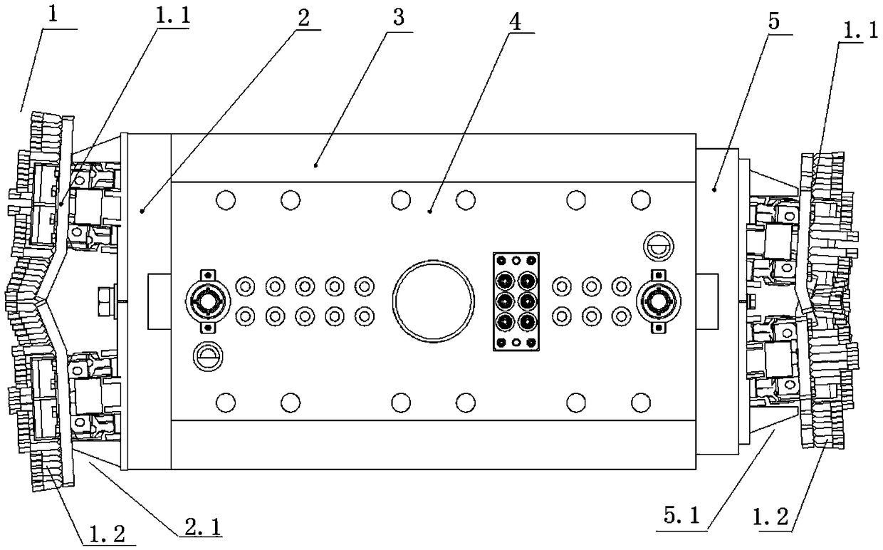
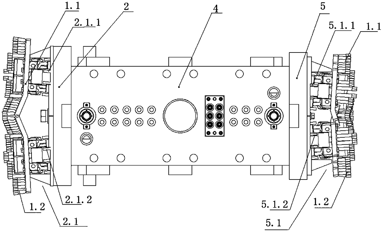
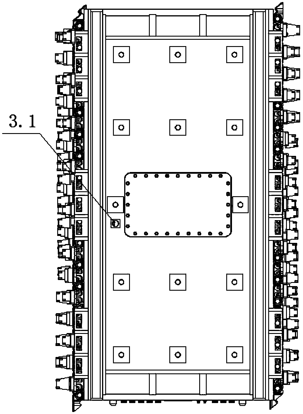
[0031] Such as Figure 2-Figure 4 As shown, a modular saw chain cutting box includes a main module box 4, a front module box 2, a rear module box 5 and a saw chain group 1, and the front mod...


PUM


Abstract

The invention discloses a modular saw chain type cutting box and a using method thereof. The cutting box comprises a body module box, a front end module box, a rear end module box and a saw chain set;the front end module box is detachably installed at the front end of the body module box; the rear end module box is detachably installed at the rear end of the body module box; a front slide rail isarranged on the outer side of the front end module box in the height direction; a rear slide rail is arranged on the outer side of the rear end module box in the height direction; the saw chain set comprises a chain and cutters installed on the chain at certain intervals; and the chain is encircled on the front slide rail and the rear slide rail to form closed loop chain transmission. The modularsaw chain type cutting box and the using method thereof can achieve modular assembling of the cutting box, can be suitable for continuous wall construction of mud protecting walls, and can be also besuitable for continuous wall construction of synchronous cutting pouring concrete.

Description

technical field [0001] The invention belongs to the technical field of building construction and relates to a cutting box, in particular to a modular saw chain type cutting box and a usage method thereof. Background technique [0002] At present, the grooves of reinforced concrete ground connecting walls are protected by artificial mud to ensure the stability of the groove walls. After the concrete is poured, even if a large amount of mud is recovered and processed for secondary treatment, a large amount of waste slurry will still be generated. If the waste slurry is directly disposed of External discharge is not conducive to green construction. The ground connection wall is generally used as the enclosure structure of the foundation pit and the water-stop system of the side wall. The traditional ground connection wall is designed in frames during construction. Seams often become frequent nodes of foundation pit leakage, resulting in potential safety hazards after excavatio...

Claims


Application Information

Patent Timeline
Patent Type & Authority Applications(China)
IPC IPC(8): E02F5/06E02F5/14E02F3/08E02F3/12E02F3/14
CPCE02F3/08E02F3/12E02F3/141E02F3/143E02F5/06E02F5/14Y02P70/10
Inventor 张琨王辉姚涛周环宇巴鑫邓雷吴全龙宋万鹏
Owner CHINA CONSTR THIRD ENG BUREAU GRP CO LTD
Why Eureka
Try Eureka