Hoist for elevator

A traction machine and elevator technology, which is applied to elevators, electric components, electromechanical devices, etc. in buildings, can solve the problems of low cooling, more components, cooling, etc., and achieve the effect of efficient cooling and less structure

Inactive Publication Date: 2011-08-10
MITSUBISHI ELECTRIC CORP
View PDF3 Cites 14 Cited by
  • Summary
  • Abstract
  • Description
  • Claims
  • Application Information

AI Technical Summary

Problems solved by technology

[0008] As mentioned above, in the invention of Patent Document 1, heat pipes are provided on both the stationary side and the rotating side, the number of parts is large, and since the cooling is performed by natural air cooling, there is a problem that is different from that of forced cooling methods such as by blowing air. The problem of low cooling performance
[0009] In addition, in the invention of Patent Document 2, the heat generated by the stator is dissipate...

Method used


Image

  • Hoist for elevator
  • Hoist for elevator
  • Hoist for elevator

Examples


no. 1 approach

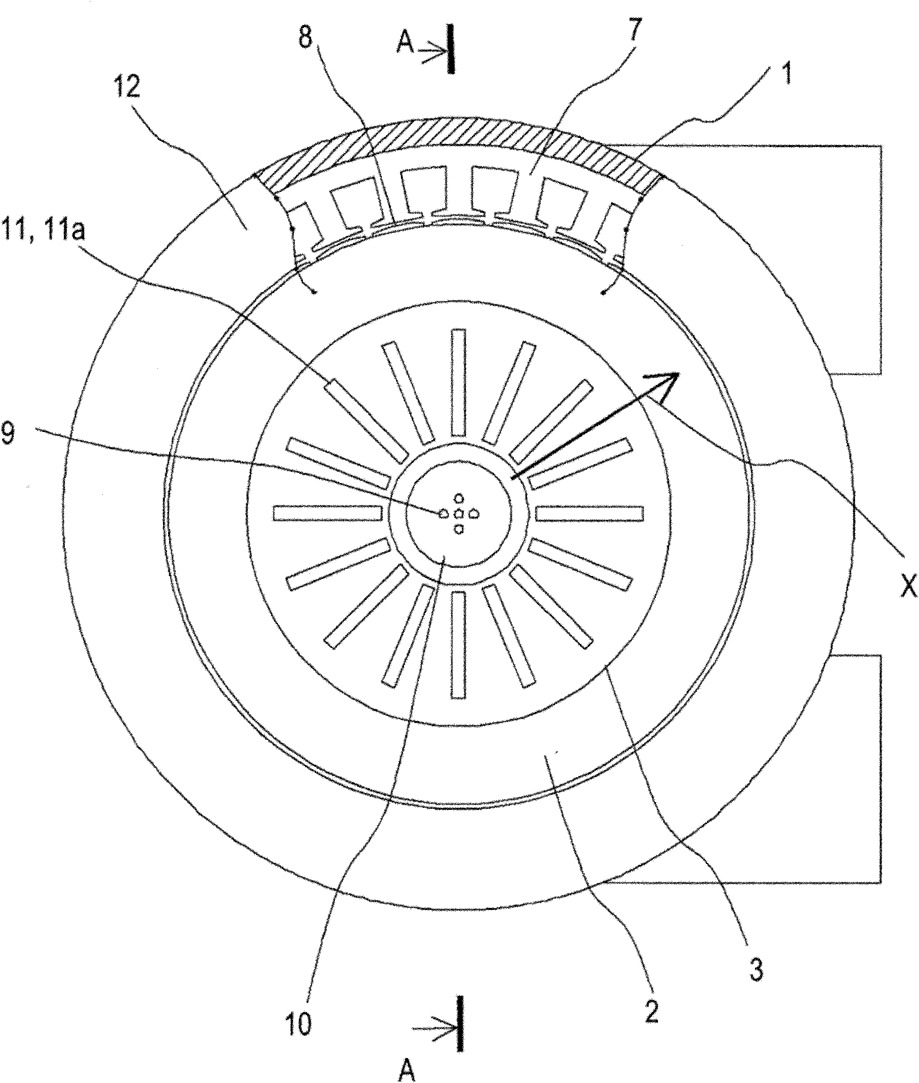
[0025] figure 1 It is a front view of the hoisting machine used in the first embodiment of the present invention. figure 2 Is showing figure 1 Figure of the A-A section.

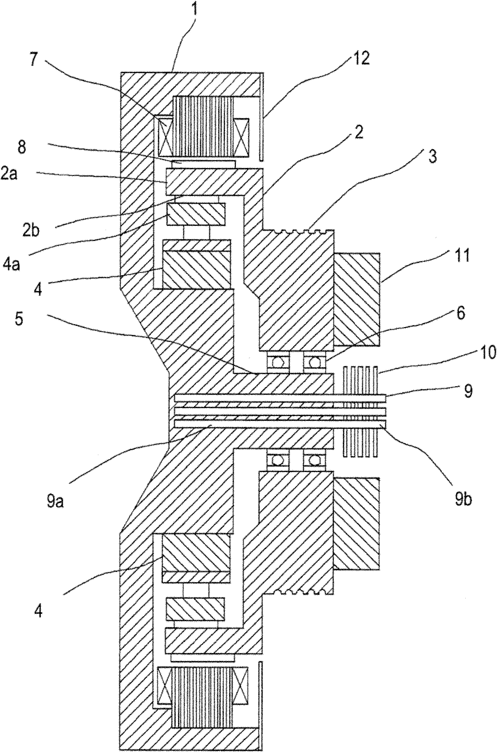
[0026] In the figure, the hoisting machine includes a fixed frame 1, a rotating body 2, a driving sheave 3, and a brake 4 that brakes the rotation of the rotating body 2. The fixed frame 1 has a bowl shape with one side open, and a spindle 5 is erected at the center of the fixed frame 1. The rotating body 2 is in the shape of a bowl with one side open, and the opening end surface 2 a is arranged inside the fixed frame 1 so as to face the bottom surface of the fixed frame 1. In addition, the rotating body 2 is rotatably supported by the main shaft 5 via a bearing 6. In addition, a stator 7 is attached to the inner peripheral surface of the fixed frame 1. In addition, the field magnet 8 and the stator 7 are mounted on the outer periphery of the rotating body 2 so as to face each other. The stator 7 and the f...

no. 2 approach

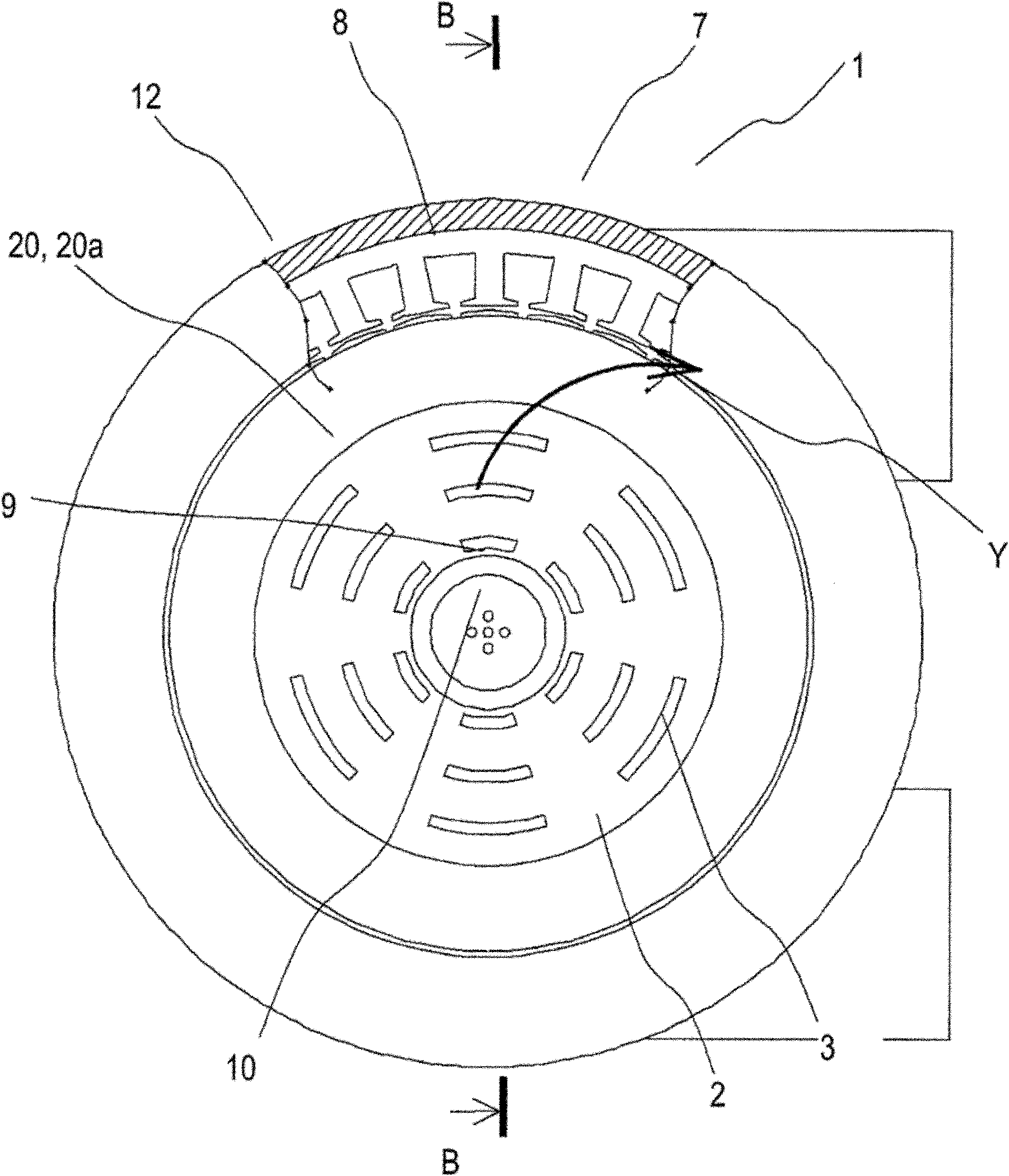
[0036] image 3 It is a front view of the hoisting machine used in the second embodiment of the present invention. Figure 4 Is showing image 3 Figure of the B-B section.

[0037] Compared with the first embodiment, the traction machine in the second embodiment changes the cooling fins provided on the rotating body 2.

[0038] On the side surface of the driving sheave 3, the cooling fin 20 is arranged around the heat dissipation fin 10. The cooling fin 20 is composed of a plurality of arc-shaped plates 20a. The arc-shaped plate 20a is in the shape of an arc concentric with the rotating body 2, and the arc-shaped plate 20a is spaced apart in the rotation direction and the radial direction. Configure it. In addition, the arc-shaped plate 20 a is formed as an arc corresponding to the same central angle of the rotation center of the rotating body 2. In addition, the arc-shaped plates 20a adjacent to each other in the rotation direction are arranged on concentric circles. Other poin...

no. 3 approach

[0050] Figure 7 It is a front view of the hoisting machine used in the third embodiment of the present invention. Compared with the second embodiment, the traction machine of the third embodiment changes the cooling fins provided on the rotating body 2.

[0051] On the side surface of the driving sheave 3, cooling fins 25 are arranged around the heat dissipation fins 10. The cooling fins 25 are composed of a plurality of arc-shaped plates 25a, and the arc-shaped plates 25a have an arc shape concentric with the rotating body 2 and are arranged at intervals in the rotation direction and the radial direction. In addition, the arc-shaped plate 25 a is formed as an arc corresponding to the same central angle of the rotation center of the rotating body 2. In addition, arc-shaped plates 25a adjacent to each other in the rotation direction are arranged on circles with different radii centered on the rotation center. The other points are the same as the second embodiment, and detailed ...


PUM


Abstract

A hoist for elevator which can be cooled efficiently when heat is generated by a simple arrangement. In the hoist for elevator, a body of revolution is supported rotatably through a bearing on a spindle standing from the central portion of a fixed frame, and a motor is constituted of a stator provided in the fixed fame, and a field magnet provided on the body of revolution and arranged oppositely to the stator. A heat pipe is inserted in the spindle while projecting partially to the outside of the spindle, and heat radiation fins are provided on the projecting portion. Cooling fins are provided at the side of the driving rope sheave and on the body of revolution and arranged around the heat radiation fins.

Description

Technical field [0001] The present invention relates to a cooling structure of an elevator hoisting machine equipped with a brake inside. Background technique [0002] A conventional traction machine is provided with a stator provided in a housing of a fixed frame body of a closed structure; a rotor as a rotating body, the rotor is equipped in the housing, and field magnets are arranged opposite to the rotor and the stator , A drive sheave is provided on one side of the rotor; and a brake is arranged on the inner surface side of the rotor. In addition, the hoisting machine includes a stationary-side heat pipe that is provided through the side surface of the housing opposite to the stator, and a rotating-side heat pipe that is provided through the side surface of the rotor opposite to the housing side. In addition, the heat in the housing is dissipated to the outside through the stationary side heat pipe, and the heat in the rotor is dissipated to the outside through the rotating...

Claims


Application Information

Patent Timeline
IPC IPC(8): H02K9/22B66B11/08
CPCH02K21/14B66B15/04H02K9/22B66B11/0438H02K7/1008H02K9/227H02K9/225B66B11/08
Inventor 木村康树户谷光利浦川英彦多田顺一
Owner MITSUBISHI ELECTRIC CORP
Why Eureka
Try Eureka