High rigidity and flexibility locating clamp and locating method of locating clamp

A flexible positioning and high-rigidity technology, used in positioning devices, clamping, manufacturing tools, etc., can solve the problems of uneven wear of the center pin and the side of the groove, high installation requirements of the combined device, affecting the positioning accuracy, etc., to achieve a simple structure. , The effect of realizing flexible automated production process, improving precision and efficiency

Active Publication Date: 2013-05-29
上海麦迅机床工具技术有限公司
View PDF1 Cites 0 Cited by
  • Summary
  • Abstract
  • Description
  • Claims
  • Application Information

AI Technical Summary

Problems solved by technology

The problem with this connecting device is that it can only be positioned in one direction in the X or Y directions. If simultaneous positioning in the X and Y directions is required, two or more connecting devices must be combined and used together, and the combined device High installation requirements
Therefore, when the work pallet is connected with the chuck for positioning, the center pin on the chuck only contacts a single side of the corresponding slot, and there is a gap between the center pin and the other side, so there are only four of the eight sides of the four slots Fitting, this kind of positioning is a rigid positioning, which will lead to uncertain positioning
In addition, the frictional force between the center pin and the side of the slot to which it fits is extremely high, which will lead to uneven wear of the center pin and the side of the slot during use, and ultimately affect the positioning accuracy, making the device suitable for use in different processing fields, especially It is difficult to use in the processing field that requires cutting rigidity, and it is not easy to promote in the automated flexible production process
[0005] In summary, the disadvantage of the existing fixture is that its rigid positioning is realized on the flexible extrusion deformation of one of the chuck and the working pallet
Under the action of heavy cutting force, the flexible extrusion deformation will cause vibration and tremor, which will make the machining accuracy of the workpiece on the working pallet out of control

Method used


Image

  • High rigidity and flexibility locating clamp and locating method of locating clamp
  • High rigidity and flexibility locating clamp and locating method of locating clamp
  • High rigidity and flexibility locating clamp and locating method of locating clamp

Examples


Embodiment Construction

[0019] The present invention will be further described below in conjunction with the accompanying drawings and embodiments.

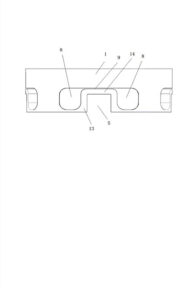
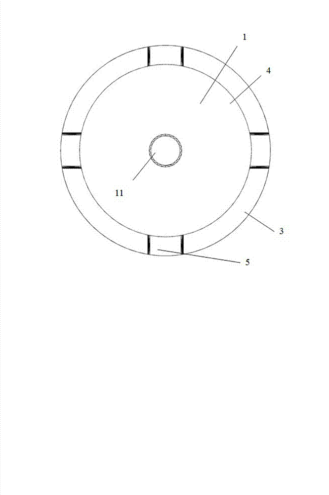
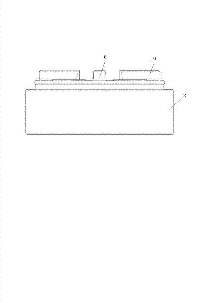
[0020] A high-rigidity flexible positioning fixture, including a workpiece supporting plate 1 and a chuck base body 2, the workpiece supporting plate 1 and the chuck base body 2 are connected by a connecting device, and it is characterized in that the lower end of the workpiece supporting plate 1 is provided with a boss 3, and the convex A Z-axis positioning surface 4 is provided on the end surface of the table 3, and a plurality of positioning grooves 5 are provided on the boss 3. A plurality of positioning teeth 6 matching with the positioning grooves 5 are provided on the upper end of the chuck base body 2, and a plurality of positioning teeth 6 are arranged on the upper end of the chuck base body 2. The Z-axis reference plane 7 matched with the Z-axis positioning plane 4 is provided with avoidance holes 8 on both sides of each positioning groove 5, a...


PUM


Abstract

The invention discloses a high rigidity and flexibility locating clamp which comprises a chuck base body and a work support plate, wherein the chuck base body and the work support plate are connected by a connecting device. The locating clamp is characterized in that the lower end of the work support plate is provided with a boss, the end surface of the boss is provided with a Z shaft locating surface, a plurality of locating grooves are arranged in the boss, the upper end of the chuck base body is provided with a plurality of locating teeth matched with the locating grooves, and the upper end of the chuck base body is provided with a Z shaft datum plane matched with the Z shaft locating surface. The side inclination of the locating teeth is 80-90 DEG, the side inclination of the locating grooves is 81-90 DEG, the side inclination of the locating grooves is 1-3 DEG bigger than that of the locating teeth, the bottom width of the locating grooves is 0.01-0.5mm smaller than the root width of the locating teeth, and both of the two sides of each locating groove are provided with dodge holes. The high rigidity and flexibility locating clamp has the advantages of high repeated locating accuracy, simple structure and low processing cost.

Description

technical field [0001] The invention relates to the technical field of positioning and clamping between machine tools and workpieces in precision machinery manufacturing, in particular to a highly rigid and flexible positioning clamp. Background technique [0002] Positioning fixtures are most commonly used for clamping with one or more workpieces. The workpieces are located at precise positions in the machining area of ​​the machine tool. The part with the workpiece is the carrier or pallet of the workpiece, and the part fixed to the machining area of ​​the machine tool is the chuck. Thereby, the production process of flexible automatic production can be realized. [0003] Chinese patent CN1443620A discloses a connecting device. The device includes a chuck and a detachable workpiece holder clamp connected to the chuck. The workpiece holder with the clamping pin is fixed in the fixture of the chuck, the chuck is provided with a central hole and a clamping mechanism, the fo...

Claims


Application Information

Patent Timeline
Patent Type & Authority Patents(China)
IPC IPC(8): B23Q3/12
Inventor 薛俊伦
Owner 上海麦迅机床工具技术有限公司
Why Eureka
Try Eureka