
Air pressure-type flushing water tank

A water tank flushing, air pressure technology, applied in flushing equipment with water tanks, water supply devices, buildings, etc., can solve problems such as failure of the water tank, no water in the water tank, rupture of the water tank, etc., to achieve water saving, better sealing performance, explosive effect

Inactive Publication Date: 2013-02-13
邝礼根
View PDF0 Cites 0 Cited by
  • Summary
  • Abstract
  • Description
  • Claims
  • Application Information

AI Technical Summary

Problems solved by technology

[0002] The traditional water tank is used to flush the toilet bowl, often due to the defect of the air valve structure of the water tank, after the air valve structure of the water tank is used for many times, it is easy to fail due to the excessive air leakage and intake of the air valve structure, causing the internal pressure of the water tank to be higher than that of tap water The pressure of the pipe will cause the water tank to rupture or conflict with each other, causing the water tank to leak out; what is more serious is that the entire water tank is full of water and the pressure of the water is too high, causing the water tank to burst
Moreover, traditional water tanks usually fail to achieve water-saving and environmental protection functions

Method used


Image

  • Air pressure-type flushing water tank
  • Air pressure-type flushing water tank
  • Air pressure-type flushing water tank

Examples


Embodiment 1

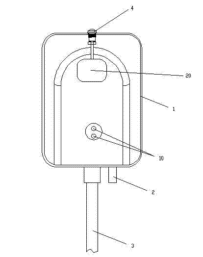
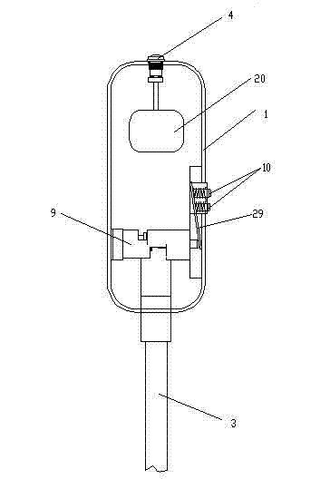
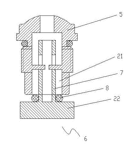
[0020] As described in Embodiment 1 of the present invention: as figure 1 , figure 2 As shown, a pneumatic flushing water tank includes a box body 1, and the box body 1 is provided with a cavity for holding water, and the box body 1 is provided with a water inlet pipe 2 and a water outlet pipe 3 communicating with the cavity, wherein the aforementioned The top of the box body 1 is provided with an intake and exhaust valve 4; image 3 As shown, the intake and exhaust valve 4 is composed of a fixed hole seat 5 passing through the top of the box body 1 and sealingly combined with the box body 1. The fixed hole seat 5 is provided with an air inlet and outlet channel 21 and A movable piston rod assembly 6 is arranged to cooperate with the air inlet and outlet channels; The lower second sealing ring 8 is composed of a floating ball 20 connected to the bottom of the piston rod 7, and the bottom of the piston rod 7 is a round block 22 that is larger than the hole diameter of the ai...


PUM


Abstract

The invention discloses an air pressure-type flushing water tank, comprising a tank body, wherein the tank body is internally provided with a cavity which is used for containing water, the tank body is provided with a water inlet pipe and a water outlet pipe which are communicated with the cavity, an air inlet outlet valve is arranged at the upper part of the tank body, and the air inlet outlet valve is composed of a fixed hole seat, an air inlet outlet hole and a movable piston rod assembly, wherein the fixed hole seat penetrates the wall part of the tank body and is combined with the tank body in a sealed way, the air inlet outlet hole is arranged on the fixed hole seat and used for communicating the inner cavity of the tank body and atmosphere, and the movable piston rod assembly is matched with the air inlet outlet hole; and the piston rod assembly is composed of a piston rod which is arranged in the air inlet outlet hole of the fixed hole seat, a second seal ring which is sheathed on the piston rod and is arranged below the fixed hole seat, and a floating ball which is connected with the bottom of the piston rod, and the bottom of the piston rod is a round block which is larger than the pore diameter of the air inlet outlet hole of the fixed hole seat. The water tank adopts a special air inlet outlet valve structure which takes air pressure in the natural environment condition as a sealing power and has superior effects on the water volume control and sealing performance of the water tank; and the air inlet outlet valve has simple structure, small volume and is convenient to use.

Description

technical field [0001] The invention relates to a water tank, in particular to an air pressure flushing water tank which maintains an air pressure balance state. Background technique [0002] The traditional water tank is used to flush the toilet bowl, often due to the defect of the air valve structure of the water tank, after the air valve structure of the water tank is used for many times, it is easy to fail due to the excessive air leakage and intake of the air valve structure, causing the internal pressure of the water tank to be higher than that of tap water The pressure of the pipe will cause the water tank to rupture or conflict with each other, causing the water tank to not produce water; what is more serious is that the entire water tank is over-pressured by the water due to being filled with water, causing the water tank to explode. Moreover, traditional water tanks usually fail to achieve the functions of water saving and environmental protection. Contents of th...

Claims


Application Information

Patent Timeline
Patent Type & Authority Patents(China)
IPC IPC(8): E03D3/10E03D1/30E03D1/34E03D1/32E03D5/09E03D5/10
Inventor 邝礼根
Owner 邝礼根
Learn More