Supercharge Your Innovation With Domain-Expert AI Agents!

Multi-channel plate-fin dew-point indirect evaporative cooling heat exchanger

A dew point indirect and evaporative cooling technology, applied in the direction of indirect heat exchangers, heat exchanger types, heat exchange equipment, etc., can solve the problems of low heat exchange efficiency and inability to be cooled to the air dew point temperature by the cooling medium, and achieve maximum temperature Reduce, improve heat exchange efficiency, reduce energy consumption

Inactive Publication Date: 2013-02-20
无锡金龙石化冶金设备制造有限公司 +1
View PDF0 Cites 0 Cited by
  • Summary
  • Abstract
  • Description
  • Claims
  • Application Information

AI Technical Summary

Problems solved by technology

In our country, research on the application of the above-mentioned theories has begun to appear and has gradually deepened. Various experimental dew point indirect evaporative cooling heat exchangers and other dew point indirect evaporative coolers have entered the testing stage, and there are also some related national patents, but they have not yet been published. It has been effectively applied in engineering practice, especially there is no dew point indirect evaporative cooling heat exchanger that can be effectively used for evaporative refrigeration in industrial engineering and ordinary civil projects, so as to effectively reduce energy consumption and energy saving and emission reduction.
In addition, the indirect evaporative cooling heat exchanger commonly used in the prior art adopts the structure of two channels of humid air and heat medium, and the heat exchange efficiency is low, and it is impossible to directly cool the cooled medium to the air dew point temperature

Method used


Image

  • Multi-channel plate-fin dew-point indirect evaporative cooling heat exchanger
  • Multi-channel plate-fin dew-point indirect evaporative cooling heat exchanger
  • Multi-channel plate-fin dew-point indirect evaporative cooling heat exchanger

Examples


Embodiment Construction

[0020] The specific implementation manners of the present invention will be further described in detail below in conjunction with the accompanying drawings.

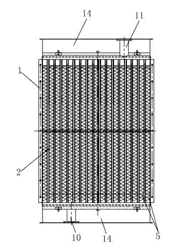
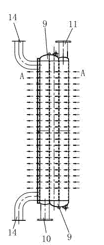
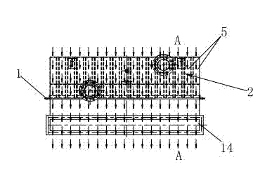
[0021] As shown in Figures 1 to 4, the present invention includes a bracket 1 and a dew point heat exchange core 2, such as Figure 4 , the dew point heat exchange core 2 is composed of several heat exchange units 3 which are adjacent to each other in sequence, and each heat exchange unit 3 is separated by a partition plate 4 and sequentially adjacent to the wet air channel 5, heat medium channel 6, wet air channel 5 and The dry air channel 7 is formed, that is to say, the channels of the dew point heat exchange core 2 are arranged and combined into the wet air channel 5, the heat medium channel 6, the wet air channel 5, the dry air channel 7, the wet air channel 5, and the heat medium channel 6 , wet air channel 5, dry air channel 7..., the multi-channel dew point heat exchange core 2 formed by this arrangement, the two...


PUM


Abstract

The invention relates to a multi-channel plate-fin dew-point indirect evaporative cooling heat exchanger, which comprises a bracket and a dew-point heat exchange core; the dew-point heat exchange core is formed by orderly adjoining a plurality of heat exchange units, wherein each heat exchange unit is divided by a separation plate and is formed by orderly adjoining a moist air channel, a heat medium channel, a moist air channel and a dry air channel; at least a layer of horizontal laminate is arranged in the heat medium channel; a vertical fin is arranged in the moist air channel; and a plurality of pores for communicating the moist air channels are arranged on the separation plates on both sides of the dry air channel. The multi-channel plate-fin dew-point indirect evaporative cooling heat exchanger is formed by combining a plurality of channels, the moist air channels and the dry air channel which are connected in parallel to exchange heat in countercurrent manner are used for cooling the heat medium in the heat medium channel; the heat exchange efficiency is improved, the air or the liquid medium can be cooled to a temperature close to an air dew point; the multi-channel plate-fin dew-point indirect evaporative cooling heat exchanger can realize more temperature drop in comparison with other evaporative cooling heat exchanger, which can reduce the energy resource consumption to achieve the aim of energy conservation and emission reduction.

Description

technical field [0001] The invention relates to a heat exchange device, in particular to a multi-channel plate-fin dew point indirect evaporative cooling heat exchanger. Background technique [0002] In 2003, Russian scholar Dr. Valeriy Maisotsenko proposed a new cycle theory of thermodynamics named after him. It uses the natural refrigeration of water to evaporate and absorb heat in the air to cool down the gas or liquid medium. It can be used without the use of compressors and refrigerants. Cool any gaseous or liquid medium to a temperature close to the dew point of air. In our country, research on the application of the above-mentioned theories has begun to appear and has gradually deepened. Various experimental dew point indirect evaporative cooling heat exchangers and other dew point indirect evaporative coolers have entered the testing stage, and there are also some related national patents, but they have not yet been published. It has been effectively applied in engi...

Claims


Application Information

Patent Timeline
Patent Type & Authority Patents(China)
IPC IPC(8): F28D9/00F28F3/08
Inventor 张宜万殷敏伟蒋彩琴余国海
Owner 无锡金龙石化冶金设备制造有限公司
Features
  • R&D
  • Intellectual Property
  • Life Sciences
  • Materials
  • Tech Scout
  • Unparalleled Data Quality
  • Higher Quality Content
  • 60% Fewer Hallucinations
Learn More