Eureka AIR delivers breakthrough ideas for toughest innovation challenges, trusted by R&D personnel around the world.

Device and method for detecting light condensation efficiency of condensing lens

A detection device and concentrating mirror technology, applied in the field of concentrating mirrors, can solve problems such as the gap in concentrating mirror light collection efficiency, uneven distribution of light energy, and uneven energy distribution, and achieve the effects of excellent construction cost, uniform distribution, and stable energy

Inactive Publication Date: 2011-08-17
GLORY SCI
View PDF3 Cites 1 Cited by
  • Summary
  • Abstract
  • Description
  • Claims
  • Application Information

AI Technical Summary

Problems solved by technology

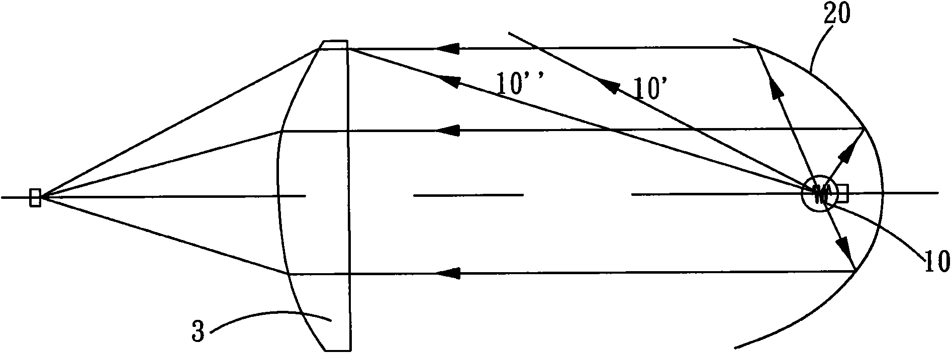
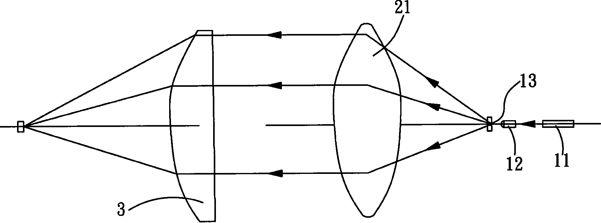
In short, even if a point light source with the same radiation energy in each direction angle is used, when a parallel beam is generated through an optical lens, the light energy distribution of each part of the parallel beam is not uniform, that is, the energy distribution of the parallel beam irradiating the condenser lens to be tested is Inhomogeneous, which is very different from the actual sunlight that is uniformly illuminated, resulting in a large gap between the light collection efficiency of the condenser lens measured using the above detection framework and when using real sunlight

Method used


Image

  • Device and method for detecting light condensation efficiency of condensing lens
  • Device and method for detecting light condensation efficiency of condensing lens
  • Device and method for detecting light condensation efficiency of condensing lens

Examples


Embodiment Construction

[0041] In order to describe the technical content, structural features, achieved goals and effects of the present invention in detail, the following will be described in detail in conjunction with the embodiments and accompanying drawings.

[0042] see Figure 3A and Figure 3B The parallel light beams of the simulated artificial solar light source in the detection method of the light collection efficiency of the concentrating lens of the present invention are provided by a stable and uniform planar light source 40 . In order to form a parallel light beam to test the condenser lens 30 to be tested, the distance between the plane light source 40 and the condenser lens 30 to be tested and the aperture diameter of the plane light source 40 need to be controlled.

[0043] Such as Figure 3A As shown, the uniform light emitted on the surface of the planar light source 40 has a large distribution angle, but when increasing the distance (L) between the planar light source 40 and th...


PUM


Abstract

The invention discloses a device and method for detecting the light condensation efficiency of a condensing lens. The method comprises the following steps: firstly, arranging a stable flat light source which emits light uniformly at one opening of a black box, and arranging a condensing lens under detection at the other opening of the black box; secondly, arranging a light sensor at the focus of the condensing lens under detection and the position of the condensing lens under detection in sequence; thirdly, recording the energy of the incident light measured by the light sensor and condensed by the condensing lens under detection and the irradiation energy of the flat light source at the position of the condensing lens under detection; fourthly, measuring the light receiving area of the condensing lens under detection and the light sensing area of the light sensor; and finally, calculating the light condensation efficiency of the condensing lens under detection by multiplying the ratio of the energy of the incident light condensed by the condensing lens under detection to the irradiation energy of the flat light source at the position of the condensing lens under detection by the ratio of the light sensing area of the light sensor to the light receiving area of the condensing lens under detection. Accordingly, the device and method for detecting the light condensation efficiency of the condensing lens can be used for detecting more stable light condensation efficiency of the condensing lens, which is more approximate to the light condensation efficiency of the condensing lens actually irradiated by sunlight.

Description

technical field [0001] The invention relates to the technical field of condenser mirrors, in particular to a detection device and method for light collection efficiency of a condenser mirror. Background technique [0002] With the improvement of living standards and the increase of population, human beings' demand and consumption of energy are increasing day by day. However, most of the way to generate energy now comes from thermal energy conversion of burning petrochemical raw materials, such as coal and oil used in power generation. As well as the diesel and gasoline used in the movement of automobiles and motorcycles, a large amount of carbon dioxide is produced as a result. When the carbon dioxide produced by human activities exceeds the self-cleaning capacity of nature, the gradual increase in carbon dioxide in the atmosphere has already formed the greenhouse effect, which in turn will lead to the warming of the earth's surface, accompanied by environmental changes such...

Claims


Application Information

Patent Timeline
IPC IPC(8): G01M11/02F21V13/00F21Y101/02F21Y115/10
Inventor 沈伟徐永明李远林
Owner GLORY SCI
Why Eureka
Eureka Blog
Learn More