Portable liquid sampling box

A portable, sampling box technology, applied in sampling devices and other directions, can solve problems such as increased work cost, lack of sealing, and reduced work efficiency, and achieve the effects of preventing air pollution, strong shock resistance, and improving efficiency

Inactive Publication Date: 2011-08-17
ZAOZHUANG POWER SUPPLY COMPANY OF STATE GRID SHANDONG ELECTRIC POWER
View PDF5 Cites 3 Cited by
  • Summary
  • Abstract
  • Description
  • Claims
  • Application Information

AI Technical Summary

Problems solved by technology

[0003] 1. Inconvenient to carry and carry
When a large amount of liquid is collected, the number of bottles and liquid samples placed in the sampling box is large, and two people are often required to carry them, which is very inconvenient during transportation and on-site use, which greatly reduces work efficiency and increases work. cost
[0004] 2. Poor durability
Due to the simple manufacturing process, especially the middle foam layer is easily damaged during use
In addition, due to the lack of effective sealing fixation, liquid samples
[0005] Leakage is prone to occur in the process of transportation and taking, and there is a problem of polluting the box
At the same time, bumps and collisions during transportation also greatly shorten the service life of sampling bottles
[0006] 3. Insufficient sealing
The traditional liquid sampling box is basically an open box without sealing, which has gradually failed to meet the requirements of the development of liquid sampling
Nowadays, the liquid sampling required for special high-precision assays requires very high sample quality, and a little carelessness can easily cause great interference to the assay data and affect the analysis results
In particular, some liquids are very sensitive to air and light. Once the sampled liquid is polluted by air or light causes chemical reactions, it will easily lead to distortion of sample data.

Method used


Image

  • Portable liquid sampling box
  • Portable liquid sampling box
  • Portable liquid sampling box

Examples


Embodiment Construction

[0031] The present invention will be further described below in conjunction with accompanying drawing and specific embodiment:

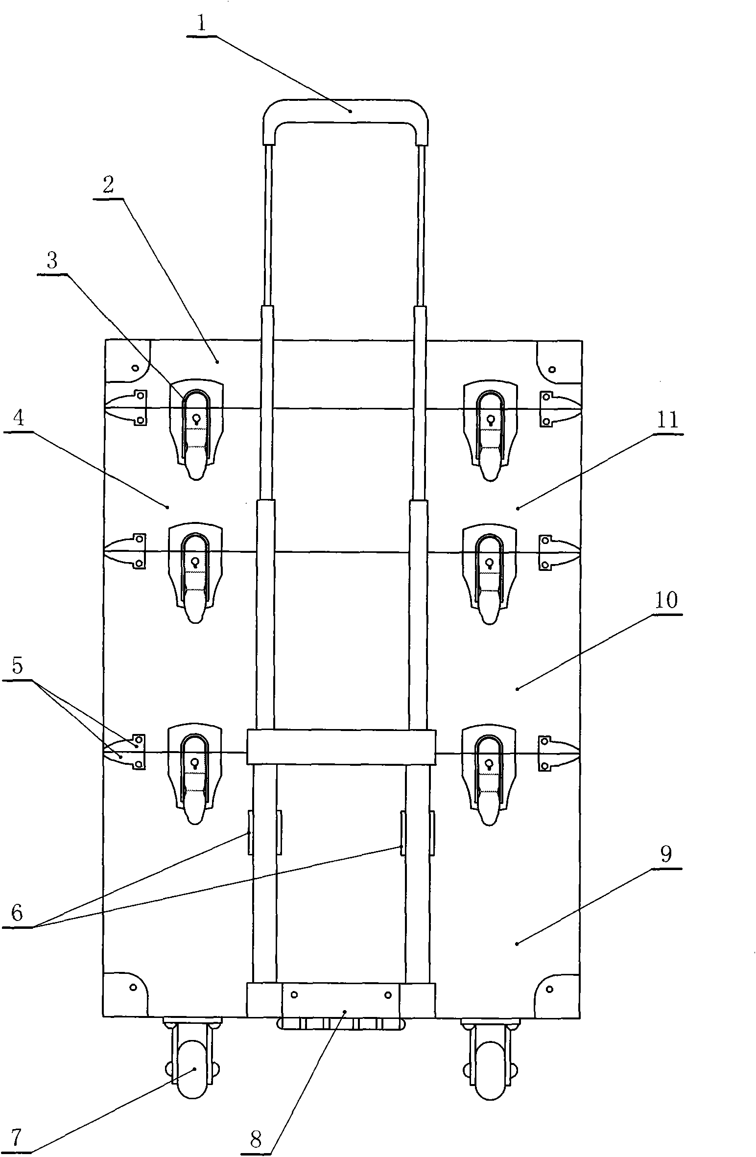
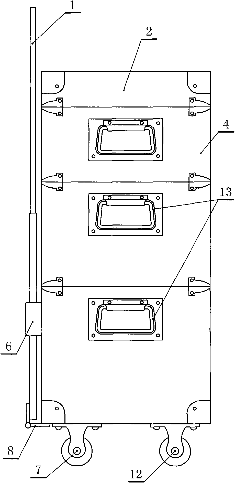
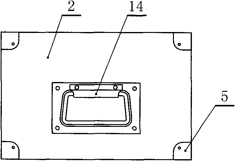
[0032] A portable liquid sampling box such as Figure 1 to Figure 4 Shown, comprise box body 4, box body 4 is provided with box cover 2 above, and box body 4 is provided with circular groove bucket 16, as Figure 8 As shown, a spring 17 is connected to the inner bottom wall of the round groove barrel 16, and a supporting plate 18 is connected to the upper end of the spring 17; The inside of the casing 4 is divided into a plurality of container tanks, and the circular tank bucket 16 is positioned in the container container, and the casing 4 includes a small bottle case 10 and a large bottle case 11 (see Figure 5 with Image 6 ); Described casing 4 includes toolbox 9, as Figure 7 As shown, the tool box 9 is divided into a funnel area 20, a large tool area 21 and a small tool area 22, and an iron box 19 is provided in the funnel area 20; a buffer s...


PUM


Abstract

The invention relates to a portable liquid sampling box which has strong isolation and seal properties, is durable in use and is convenient to transport. The portable liquid sampling box comprises a box body on which a box cover is arranged; the box body is internally provided with circular groove barrels; the inner bottom wall of each circular groove barrel is connected with a spring; the upper end of each spring is connected with a supporting plate; the box body is divided into a plurality of layers, and every two adjacent layers are fastened together in the vertical direction; the box body is internally divided into a plurality of utensil tanks in which the circular groove barrels are arranged; the box body comprises a large bottle box, a small bottle box and a tool box, wherein the tool box is internally divided into a funnel area, a large tool area and a small tool area; the funnel area is internally provided with an iron case; the top wall of the box cover is internally connected with a buffer sponge; the inner side walls and the bottom wall of the box body are connected with buffer sponges; the inner side walls of the circular groove barrels are also connected with buffer sponges; a universal wheel and a directional wheel are fixed below the box body; an expansion handle is hinged on the box body through a hinge; elastic clamping slots are fixedly arranged on the side walls of the box body; and the expansion handle is clamped in the elastic clamping slots.

Description

technical field [0001] The invention relates to a storage device for sampling bottles, in particular to a portable liquid sampling box. Background technique [0002] After a large number of investigations, it was found that most of the sampling boxes used in liquid sampling are relatively simple and primitive in structure at present. Many users make simple wooden or iron boxes according to their own liquid sampling needs, and a simple bottle slot is made of foam in the middle. Sampling boxes for field use. There are many deficiencies in this type of liquid sampling box: [0003] 1. It is inconvenient to carry and carry. When a large amount of liquid is collected, the number of bottles and liquid samples placed in the sampling box is large, and two people are often required to carry them, which is very inconvenient during transportation and on-site use, which greatly reduces work efficiency and increases work. cost. [0004] 2. Poor durability. Due to the simple manufact...

Claims


Application Information

Patent Timeline
Patent Type & Authority Applications(China)
IPC IPC(8): G01N1/10
Inventor 宋士贤周国卿田传银韩帅余磊孙忠凯
Owner ZAOZHUANG POWER SUPPLY COMPANY OF STATE GRID SHANDONG ELECTRIC POWER
Why Eureka
Try Eureka