Yacht monitoring device and system

A monitoring device and yacht technology, applied in general control systems, control/regulation systems, program control, etc., can solve the problems of poor applicability and high construction cost of yacht monitoring devices, and achieve the effects of saving monitoring costs and strong applicability

Inactive Publication Date: 2011-08-17
DALIAN JIAOTONG UNIVERSITY
6 Cites 8 Cited by

AI-Extracted Technical Summary

Problems solved by technology

[0004] The purpose of the embodiments of the present invention is to provide a yacht monitoring device to solve the problem that the yacht monitoring device provided by the prior a...

Abstract

The invention discloses a yacht monitoring device and a yacht monitoring system. The yacht monitoring device comprises: a status information acquisition unit, a control unit, a first wireless communication unit, and a power supply unit. The status information acquisition unit is used for acquiring status information of a yacht in operation; the control unit is used for analyzing the status information acquired by the status information acquisition unit to obtain status result information of yacht operation; the first wireless communication unit is used for transmitting the status result information obtained by the control unit to a monitoring terminal arranged in a master control room at a coast station for display based on a short-distance wireless communication protocol; and the power supply unit is used for supplying power to the status information acquisition unit, the control unit and the first wireless communication unit. After obtaining the status result information of the yacht operation, the device transmits the status result information to the monitoring terminal arranged in the master control room at the coast station for display through the short-distance wireless communication protocol, so the construction based on an automatic identification system (AIS) is avoided, the monitoring cost is saved, the applicability is strong, and the device is particularly suitablefor monitoring the sailing yacht in a certain sea area in real time.

Application Domain

Technology Topic

Short range wirelessCommunication unit +12

Image

  • Yacht monitoring device and system
  • Yacht monitoring device and system
  • Yacht monitoring device and system

Examples

  • Experimental program(1)

Example Embodiment

[0023] In order to make the objectives, technical solutions and advantages of the present invention clearer, the following further describes the present invention in detail with reference to the accompanying drawings and embodiments. It should be understood that the specific embodiments described herein are only used to explain the present invention, but not to limit the present invention.
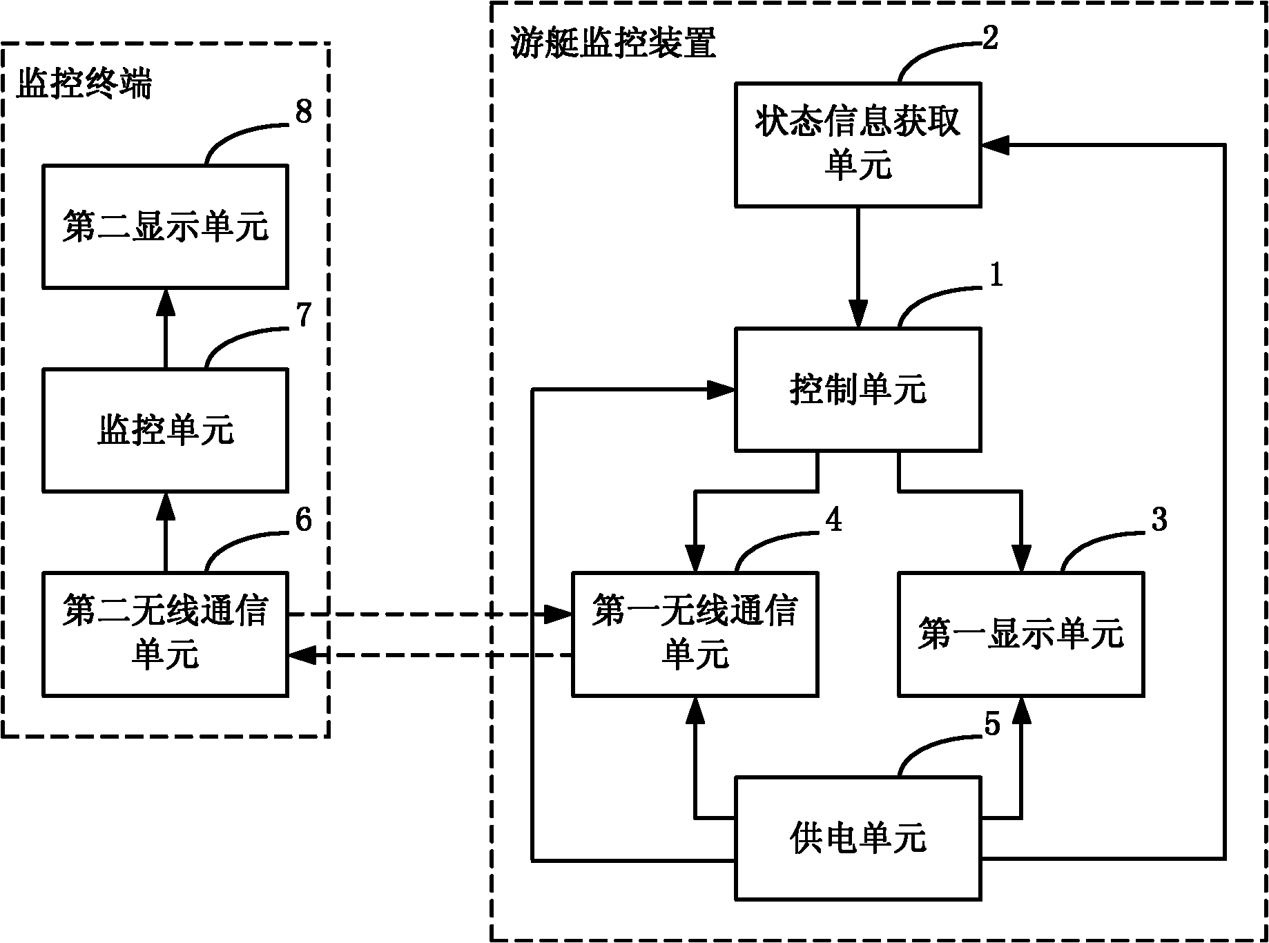
[0024] The yacht monitoring system provided by the embodiment of the present invention obtains the status result information of the yacht operation through the yacht monitoring device on the yacht, and uses the short-distance wireless communication protocol to send the status result information to the monitoring terminal placed in the main control room of the shore station and then display it .
[0025] figure 1 It shows the structural principle of the yacht monitoring system provided by the embodiment of the present invention. For ease of description, only the parts related to the embodiment of the present invention are shown.
[0026] The yacht monitoring system provided by the embodiment of the present invention includes: a yacht monitoring device placed on the yacht, which is used to obtain status information of the running yacht, and after analyzing the status information of the yacht operation based on the status information, it is based on short-range wireless communication Protocol sending; and a monitoring terminal placed in the main control room on the shore station, which is used to display the status result information sent by the yacht monitoring device based on the corresponding short-range wireless communication protocol.
[0027] The status information of the yacht is one or a combination of the global positioning system (GPS) positioning parameter information of the yacht, the tilt angle information of the yacht, and the electric quantity information of the battery pack that provides electric energy for the operation of the yacht.
[0028] When the status information is the GPS positioning parameter information of the yacht, the steps of the yacht monitoring device analyzing and obtaining the status result information of the yacht operation according to the status information are specifically as follows: the yacht monitoring device extracts the yacht's longitude value and the value from the GPS positioning parameter information. One or more of the latitude value, speed value, and time value. If the yacht monitoring device extracts the longitude value, latitude value and/or speed value of the yacht from the GPS positioning parameter information, the longitude value and latitude value and / Or the speed value is the status result information of the yacht operation; if the yacht monitoring device extracts the time value of the yacht from the GPS positioning parameter information, the yacht monitoring device determines the use of the yacht according to the time value and the pre-stored yacht start time value Time, the use time is the status result information of the yacht operation. In addition, after extracting the longitude and latitude values ​​of the yacht, the yacht monitoring device can further determine whether the longitude value is within the preset longitude value range indicating safe waters, and determine whether the latitude value is within the preset indicating safety If the latitude of the water is within the range, no action or safety prompt information will be generated. Otherwise, an out-of-bounds alarm prompt message will be generated. The status result information can also include the safety prompt information and the out-of-boundary alarm prompt information; the yacht monitoring device is extracting the yacht speed value After that, it can be further judged whether the speed value exceeds the preset speed value. If yes, an overspeed warning message will be generated. Otherwise, no action or safety message will be generated. The status result information may also include the safety message and overspeed warning message; After determining the usage time of the yacht, the monitoring device can further determine whether the usage time exceeds the preset time, and if yes, it will send out an overtime alarm prompt message, otherwise it will not act or generate safety prompt information. The status result information can also include the safety prompt information And overtime alarm prompt information.
[0029] When the status information is the inclination angle information of the yacht, the steps of the yacht monitoring device analyzing and obtaining the status result information of the yacht operation according to the status information are specifically as follows: the yacht monitoring device obtains the inclination direction of the yacht and the corresponding inclination angle according to the inclination angle information , The inclination direction and the corresponding inclination angle are the result information of the yacht running status. In addition, after obtaining the inclination direction and corresponding inclination angle of the yacht, the yacht monitoring device can further determine whether the inclination angle exceeds the preset safety angle, and if yes, it will generate a tilt alarm prompt message, otherwise it will not act or generate a safety prompt message. , The status result information may also include the safety prompt information and the tilt alarm prompt information.
[0030] When the status information is the power information of the battery pack, the steps of the yacht monitoring device analyzing and obtaining the status result information of the yacht operation according to the status information are specifically: the yacht monitoring device determines the current power of the battery pack according to the power information of the battery pack. Status result information of yacht operation. In addition, after the yacht monitoring device determines the current power of the battery pack, it can further determine whether the current power is lower than the preset value of the total power. If yes, it will generate a low power warning message, otherwise it will not act or generate a safety message. The result information may also include the safety prompt information and the low battery alarm prompt information.
[0031] After the yacht monitoring device provided by the embodiment of the present invention obtains the status result information of the yacht operation, it uses the short-range wireless communication protocol to send the status result information to the monitoring terminal placed in the main control room of the shore station and display it, thereby avoiding the need to be based on the AIS system The construction saves the cost of monitoring, and is especially suitable for real-time monitoring of yachts sailing in a certain sea area, with strong applicability.
[0032] Specifically, the monitoring terminal includes: a second display unit 8; a second wireless communication unit 6 for receiving status result information sent by a yacht monitoring device based on a corresponding short-range wireless communication protocol; a monitoring unit 7 for controlling the second display The unit 8 displays the status result information received by the second wireless communication unit 6.
[0033] Specifically, the yacht monitoring device includes: a status information acquiring unit 2 for acquiring status information of a running yacht; a control unit 1 for analyzing the status information acquired by the status information acquiring unit 2 to obtain result information about the status of the yacht running; A wireless communication unit 4 is used to send the status result information obtained by the control unit 1 based on the short-range wireless communication protocol; and a power supply unit 5 is used to supply power to the status information acquisition unit 2, the control unit 1, and the first wireless communication unit 4. In addition, the yacht monitoring device may further include: a first display unit 3 for displaying the status result information obtained by the control unit 1 on site, and the power supply unit 5 is also used for supplying power to the first display unit 3 at this time.
[0034] Of course, in specific implementation, the second wireless communication unit 6 placed in the monitoring terminal can also issue control instructions to the other control units of the yacht to the first wireless communication unit 4 based on the short-range wireless communication protocol and/or provide the embodiments of the present invention. Control instructions for each component of the yacht monitoring device.
[0035] figure 2 show figure 1 The specific structure of the state information acquiring unit 2.
[0036] When the status information of the yacht is GPS positioning parameter information of the yacht, the status information acquiring unit 2 at least includes a GPS signal receiving unit 21 for acquiring GPS positioning parameter information of the yacht in operation. At this time, the steps for the control unit 1 to analyze the status result information of the yacht operation according to the GPS positioning parameter information acquired by the GPS signal receiving unit 21 are as described above, and will not be repeated here.
[0037] When the status information of the yacht is the inclination angle information of the yacht, the status information acquiring unit 2 at least includes: an inclination monitoring unit 22 for acquiring the inclination angle information of the yacht in operation. At this time, the control unit 1 analyzes and obtains the result information of the operating state of the yacht according to the inclination angle information acquired by the inclination angle monitoring unit 22 as described above, and will not be repeated here.
[0038] When the status information of the yacht is the power information of the battery pack, the status information acquiring unit 2 at least includes: a battery pack monitoring unit 23 for acquiring the power information of the battery pack of the running yacht. At this time, the steps for the control unit 1 to analyze the power information of the battery pack obtained by the battery pack monitoring unit 23 to obtain the result information of the operating state of the yacht are as described above, and will not be repeated here.
[0039] image 3 show figure 1 The specific structure of the control unit 1.
[0040] When the status information is the GPS positioning parameter information of the yacht, the control unit 1 at least includes: a positioning parameter signal receiving module 101 for acquiring GPS positioning parameter information of the yacht in operation; a third signal extraction module 102 for obtaining the positioning parameter signal The GPS positioning parameter information obtained by the receiving module 101 extracts the yacht's longitude and latitude values; the third alarm signal generating module 105 is used to determine whether the longitude value extracted by the third signal extraction module 102 is in a preset indicating safe water area Within the longitude value range, and determine whether the latitude value extracted by the third signal extraction module 102 is within the preset latitude value range representing the safe water area, if yes, no action is taken or a safety prompt message is generated, otherwise a cross-border alarm prompt message is generated; The signal extraction module 103 is used to extract the speed value of the yacht from the GPS positioning parameter information obtained by the positioning parameter signal receiving module 101; the first alarm signal generating module 106 is used to determine whether the speed value extracted by the first signal extraction module 103 is If it exceeds the preset speed value, it will generate a speeding warning message, otherwise it will not act or generate a safety message; the second signal extraction module 104 is used to extract the yacht’s information from the GPS positioning parameter information acquired by the positioning parameter signal receiving module 101 Time value; calculation module 118, used to determine the use time of the yacht using the time difference algorithm according to the time value extracted by the second signal extraction module 104 and the pre-stored yacht start time value; the second alarm signal generation module 107 is used to determine The calculation module 118 determines whether the use time exceeds the preset time, if yes, a timeout alarm prompt message is issued, otherwise, no action is taken or a safety prompt message is generated.
[0041] When the status information is the inclination angle information of the yacht, the control unit 1 at least includes: an inclination parameter signal receiving module 108 for acquiring the inclination angle information of the yacht in operation; an analog-to-digital conversion module 109 for receiving an inclination parameter signal The acquired analog tilt angle information is converted into a digital signal; the first identification module 110 is configured to obtain the tilt direction of the yacht and the corresponding tilt angle according to the digital signal converted by the analog-to-digital conversion module 109; the first judgment module 111 uses To determine whether the tilt angle obtained by the first identification module 110 exceeds the preset safety angle; the fourth alarm signal generating module 112 is used for when the first judging module 111 determines that the tilt angle obtained by the first identification module 110 exceeds the preset safety angle When the angle is angled, a tilt warning prompt message is generated, and when the first judging module 111 determines that the tilt angle obtained by the first recognition module 110 does not exceed the preset safety angle, no action is taken or a safety prompt message is generated.
[0042] When the status information is the power information of the battery pack of the yacht, the control unit 1 at least includes: a power parameter signal receiving module 113 for acquiring the power information of the battery pack of the running yacht; and a second identification module 116 for receiving power information according to the power parameter The power information of the battery pack obtained by the signal receiving module 113 determines the current power of the battery pack; the second determining module 114 is configured to determine whether the current power of the battery pack determined by the second identification module 116 is lower than the preset value of the total power; The fifth alarm signal generating module 115 is used to generate a low battery alarm prompt message when the second judgment module 114 judges that the current power of the battery pack determined by the second identification module 116 is lower than the preset value of the total power, and when the second judgment module 114 determines 114. When it is determined that the current power of the battery pack determined by the second identification module 116 is not lower than the preset value of the total power, no action is taken or a safety prompt message is generated.
[0043] In addition, the control unit 1 further includes: a display control module 117 for controlling the first display unit 3 to display the status result information obtained by the control unit 1 on site, so as to facilitate the on-site monitoring of the yacht's operating conditions by the yacht personnel.
[0044] In the embodiment of the present invention, the control unit 1 may be integrated in various existing programmable control chips or programmable control chipsets that can change control countermeasures through programming or software configuration. Preferably, the control unit 1 is integrated in a single-chip microcomputer. In the chip, such as Figure 4 show figure 1 A circuit of the control unit 1 in the middle, and the control unit 1 is implemented by a single-chip microcomputer chip U1.
[0045] When the control unit 1 is integrated into the single-chip microcomputer chip U1, the inclination monitoring unit 22 provided in the embodiment of the present invention can monitor the yacht's left and right tilt, bow/stern tilt up and down, and yacht up and down bumps. Figure 5 show figure 2 A circuit of the inclination angle monitoring unit 22.
[0046] The inclination monitoring unit 22 includes: a three-axis acceleration sensor chip U2, resistor R11, resistor R12, resistor R13, resistor R14, resistor R15, resistor R16, resistor R17, resistor R18, resistor R19, capacitor C16, capacitor placed parallel to the yacht hull C17, capacitor C18 and capacitor C19. Among them, the Z axis of the triaxial acceleration sensor chip U2 is perpendicular to the yacht hull, and the Y axis of the triaxial acceleration sensor chip U2 is parallel to the stern of the yacht hull along the bow direction; the first g sensing input pin of the triaxial acceleration sensor chip U2 g-select1 is connected to a 3.3V direct current through a resistor R11, the first g-sensing input pin g-select1 is also grounded through a resistor R12; the second g-sensing input pin g-select2 of the three-axis acceleration sensor chip U2 is connected to 3.3 through a resistor R13 V DC, the second g-sensing input pin g-select2 is also grounded through the resistor R14; the power input pin VDD of the three-axis acceleration sensor chip U2 is connected to 3.3V DC, and the power ground pin VSS of the three-axis acceleration sensor chip U2 is grounded The power input pin VDD is also connected to the power ground pin VSS through a capacitor C16; the sleep mode selection pin Sleep-mode of the three-axis acceleration sensor chip U2 is connected to a 3.3V direct current through a resistor R15, and the sleep mode selection pin Sleep- mode is also grounded through resistor R16; the Z-axis analog voltage output pin Zout of the three-axis acceleration sensor chip U2 is connected to the first analog signal receiving pin AN02 of the microcontroller chip U1 through a resistor R17. The Z-axis analog voltage output pin Zout is also connected The second analog voltage output pin Yout of the three-axis acceleration sensor chip U2 is connected to the second analog signal receiving pin AN01 of the microcontroller chip U1 through the resistor R17 and the capacitor C17. The Y-axis analog voltage output pin Yout At the same time, the X-axis analog voltage output pin Xout of the three-axis acceleration sensor chip U2 is connected to the third analog signal receiving pin AN00 of the microcontroller chip U1 through the resistor R19, and the X-axis analog voltage output leads Pin Xout is connected to ground through resistor R19 and capacitor C19 in sequence at the same time. When the tilt angle monitoring unit 22 with this circuit structure monitors the yacht, the simulated tilt angle information is represented by the simulated voltage value. By pre-programming the single-chip microcomputer chip U1, the change in the simulated voltage value represents the direction of the yacht's tilt. For example, when the analog voltage value received by the third analog signal receiving pin AN00 of the single-chip microcomputer chip U1 increases, it means that the yacht is tilted to the right. When the analog voltage value decreases, it means that the yacht is tilted to the left. When the analog voltage value received by the second analog signal receiving pin AN01 of the chip U1 increases, it indicates that the bow of the yacht is tilted. When the analog voltage value received by the second analog signal receiving pin AN01 of the microcontroller chip U1 decreases , Which characterizes the bow of the yacht, and the change of the analog voltage value received by the first analog signal receiving pin AN02 of the microcontroller chip U1 characterizes the up and down bumps of the yacht.
[0047] When the control unit 1 is integrated in the single-chip microcomputer chip U1, in order to realize the conversion between the TTL level signal output by the single-chip chip U1 and the CMOS level signal received by the wireless communication unit 4 and the first display unit 3, and realize the input of the single chip U1 Conversion of TTL level signals and CMOS level signals output by the battery monitoring unit 23 and GPS signal receiving unit 21. The yacht monitoring device provided by the embodiment of the present invention further includes a connection to the wireless communication unit 4, the first display unit 3, The level conversion unit between the battery monitoring unit 23 and the GPS signal receiving unit 21 and the microcontroller chip U1, such as Image 6 A circuit of the level conversion unit provided by the embodiment of the present invention is shown.
[0048] The level conversion unit includes: a first level conversion chip U3 and a second level conversion chip U4. Among them, the first signal output pin T1out of the first data channel of the first level conversion chip U3 and the first signal input pin R1in of the first data channel of the first level conversion chip U3 are connected to the wireless communication unit through the serial port J5 4. The second signal input pin T1in of the first data channel of the first level conversion chip U3 is connected to the first parallel port pin PS1 of the microcontroller chip U1, and the second signal of the first data channel of the first level conversion chip U3 The input pin R1out is connected to the second parallel port pin PS0 of the microcontroller chip U1; the first signal output pin T2out of the second data channel of the first level conversion chip U3 and the second data channel of the first level conversion chip U3 The first signal input pin R2in is connected to the first display unit 3 through the serial port J6, and the second signal input pin T2in of the second data channel of the first level conversion chip U3 is connected to the third parallel port pin PS3 of the microcontroller chip U1. The second signal output pin R2out of the second data channel of a level conversion chip U3 is connected to the fourth parallel port pin PS2 of the single-chip microcomputer chip U1.
[0049] The first signal output pin T1out of the first data channel of the second level conversion chip U4 and the first signal input pin R1in of the first data channel of the second level conversion chip U4 are connected to the GPS signal receiving unit 21 through the serial port J7 , The second signal input pin T1in of the first data channel of the second level conversion chip U4 is connected to the fifth parallel port pin PT1 of the microcontroller chip U1, and the second signal input of the first data channel of the second level conversion chip U4 Pin R1out is connected to the sixth parallel port pin PT0 of the single-chip microcomputer chip U1; the first signal output pin T2out of the second data channel of the second level conversion chip U4 and the first signal output pin T2out of the second data channel of the second level conversion chip U4 A signal input pin R2in is connected to the battery pack monitoring unit 23 through the serial port J8. The second signal input pin T2in of the second data channel of the second level conversion chip U4 is connected to the seventh parallel port pin PT3 of the single-chip microcomputer chip U1. The second signal output pin R2out of the second data channel of the level conversion chip U4 is connected to the eighth parallel port pin PT2 of the microcontroller chip U1.
[0050] When the control unit 1 is integrated into the single-chip microcomputer chip U1, the tilt angle monitoring unit 22 adopts the circuit structure described above, and the GPS signal receiving unit 21, the battery pack monitoring unit 23, the wireless communication unit 4, and the first display unit 3 adopt a universal design. When the control unit 1, the GPS signal receiving unit 21, the battery pack monitoring unit 23, the wireless communication unit 4, and the first display unit 3 are powered by 5V direct current, the inclination monitoring unit 22 is powered by 3.3V direct current. For this reason, the embodiment of the present invention The power supply unit 5 includes: a power supply module 53 that outputs 24V direct current; a second voltage adjustment module 52 is used to convert the 24V direct current output from the power supply module 53 into 5V direct current, and then output to the control unit 1, the GPS signal receiving unit 21, The battery pack monitoring unit 23, the wireless communication unit 4, and the first display unit 3; the first voltage adjustment module 51 for converting the 5V direct current converted by the second voltage adjustment module 52 into 3.3V direct current, and then output to the tilt angle monitoring unit twenty two. Of course, the power supply unit 5 may also use multiple power modules to supply power to the control unit 1, the wireless communication unit 4, the first display unit 3, the GPS signal receiving unit 21, the tilt monitoring unit 22, and the battery pack monitoring unit 23 respectively.
[0051] Such as Figure 8 Further shows Figure 7 In the first voltage adjustment module 51 of a circuit.
[0052] The first voltage adjustment module 51 includes: a first voltage regulator chip U4, a capacitor C25, a capacitor C26, a capacitor C27, an inductor L4, and a voltage regulator tube D1. Among them, the voltage input pin Vin of the first voltage regulator chip U4 is connected to the power module 53, the voltage output pin Vout of the first voltage regulator chip U4 is connected to one end of the inductor L4, and the other end of the inductor L4 serves as the first voltage adjustment module The output terminal of 51 outputs 5V direct current; the voltage output pin Vout of the first regulator chip U4 is connected to the cathode of the regulator tube D1, and the anode of the regulator tube D1 is grounded; the other end of the inductor L4 passes through the capacitor C31 and the capacitor C32 respectively Ground; the voltage input pin Vin of the first regulator chip U4 is also grounded through the capacitor C30.
[0053] Such as Picture 9 Further shows Figure 7 A circuit in the second voltage adjustment module 52.
[0054] The second voltage adjustment module 52 includes: a second voltage regulator chip U5, a capacitor C28, a capacitor C29, a capacitor C30, and a capacitor C31. The voltage input pin Vin of the second voltage regulator chip U5 is connected to the output terminal of the first voltage adjustment module 51, and the voltage output pin Vout of the second voltage regulator chip U5 serves as the output terminal of the second voltage adjustment module 52. 3.3V DC, the voltage adjustment pin ADJ of the second regulator chip U5 is grounded; the voltage input pin Vin of the second regulator chip U5 is also grounded through the capacitor C28, and the voltage output pin of the second regulator chip U5 Vout is also grounded through capacitor C29, capacitor C30, and capacitor C31.
[0055] In addition, the fifth alarm signal generating module 115 can issue a multi-level alarm for the current power of the battery pack. In the embodiment of the present invention, the fifth alarm signal generating module 115 issues a two-level alarm for the current power of the battery pack. The alarm signal generating module 115 generates a low-level warning message when the second determining module 114 determines that the current power of the battery pack determined by the second identifying module 116 is less than 10% of the total power; the fifth alarm signal generating module 115 is currently The second judging module 114 determines that the current power of the battery pack determined by the second identification module 116 is less than 5% of the total power and generates a low-battery level two warning message. In order to enable the on-site personnel to know the power of the yacht battery pack, the present invention The yacht monitoring device provided by the embodiment further includes an alarm prompt unit connected to the control unit 1, and the alarm prompt unit is specifically connected to the fifth alarm signal generating module 115 in the control unit 1, such as Picture 10 A circuit of the alarm prompt unit is shown.
[0056] The alarm prompt unit includes a resistor R19, a resistor R20, a light-emitting diode D2, and a light-emitting diode D3. One end of the resistor R20 is connected to the control unit 1, the other end of the resistor R20 is connected to the anode of the light-emitting diode D2, and the cathode of the light-emitting diode D2 is grounded; one end of the resistor R21 is connected to the control unit 2, and the other end of the resistor R21 is connected to the anode of the light-emitting diode D3 , The cathode of the light-emitting diode D3 is grounded. The light emitting diode D2 emits a yellow light according to the low battery level alarm prompt information generated by the fifth alarm signal generating module 115, and the light emitting diode D3 emits red light according to the low battery level alarm prompt information generated by the fifth alarm signal generating module 115.
[0057] The embodiment of the present invention also provides a yacht monitoring device as described above.
[0058] After the yacht monitoring device provided by the embodiment of the present invention obtains the status result information of the yacht operation, it uses the short-range wireless communication protocol to send the status result information to the monitoring terminal placed in the main control room of the shore station and display it, thereby avoiding the need to be based on the AIS system The construction saves the cost of monitoring, and is especially suitable for real-time monitoring of yachts sailing in a certain sea area, with strong applicability.
[0059] The above are only preferred specific embodiments of the present invention, but the protection scope of the present invention is not limited to this. Anyone familiar with the technical field within the technical scope disclosed by the present invention, according to the technical solution of the present invention Equivalent replacements or changes to its inventive concept should all fall within the protection scope of the present invention.

PUM

no PUM

Description & Claims & Application Information

We can also present the details of the Description, Claims and Application information to help users get a comprehensive understanding of the technical details of the patent, such as background art, summary of invention, brief description of drawings, description of embodiments, and other original content. On the other hand, users can also determine the specific scope of protection of the technology through the list of claims; as well as understand the changes in the life cycle of the technology with the presentation of the patent timeline. Login to view more.

Similar technology patents

Classification and recommendation of technical efficacy words

  • Reduce monitoring costs
  • Strong applicability

Intelligent assisted driving method and system

Owner:CHINA UNIV OF GEOSCIENCES (WUHAN)

Method and device for identifying image definition

ActiveCN105809704AIdentify wellStrong applicabilityImage enhancementImage analysisRegion of interestDistinctness of image
Owner:BEIJING XIAOMI MOBILE SOFTWARE CO LTD
Why Eureka
Try Eureka