
High-power induction charging converter of electric vehicle and control method thereof

A technology for electric vehicles and inductive charging, applied in electric vehicles, AC power input is converted into AC power output, current collectors, etc. Effect

Inactive Publication Date: 2011-08-17
SOUTHEAST UNIV
View PDF4 Cites 25 Cited by
  • Summary
  • Abstract
  • Description
  • Claims
  • Application Information

AI Technical Summary

Problems solved by technology

Its outstanding feature is that the power-frequency AC power is converted into DC power through a three-phase rectifier, and then the DC power is converted into high-frequency AC power through a full-bridge inverter, and then the AC power is transmitted to the secondary circuit through a loosely coupled transformer. The transformer is a loosely coupled transformer with a low coupling coefficient, and the transmission efficiency is low. Therefore, it is necessary to convert the power frequency alternating current into high frequency alternating current, reduce the volume of the coupling transformer, and compensate the primary and secondary sides of the coupling transformer to increase the power. transmission efficiency

Method used


Image

  • High-power induction charging converter of electric vehicle and control method thereof
  • High-power induction charging converter of electric vehicle and control method thereof
  • High-power induction charging converter of electric vehicle and control method thereof

Examples


Embodiment Construction

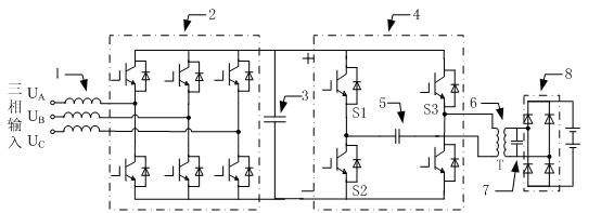
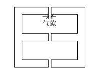
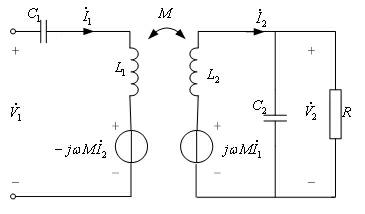
[0027] The high-power electric vehicle inductive charging converter device proposed by the present invention adopts the bridge rectification topology structure of six full-control switches in three phases, the high-frequency inverter topology of the single-phase full-bridge inverter circuit, and the primary side series compensation of loosely coupled transformers , The topology structure of secondary side parallel compensation. Each phase of the three-phase rectifier circuit is connected to a reactor on the AC side, and the DC side is connected to a DC energy storage capacitor; the inverter circuit is a full-bridge inverter circuit; the transformer adopts a loosely coupled transformer with separated primary and secondary sides, and the air gap of the transformer is long , the coupling coefficient is less than 0.5; the inductive coupling circuit series compensation capacitor is connected to the primary side of the loosely coupled transformer, and the secondary side is connected ...


PUM


Abstract

The invention provides a high-power induction charging converter of an electric vehicle and a control method thereof. The converter comprises a three-phase fully-controlled bridge rectifying circuit, a full-bridge inverter circuit and an inductive coupling circuit which are connected in sequence, wherein each phase at the alternating current (AC) side of the three-phase rectifying circuit is connected with a reactor (1), the three-phase rectifying circuit is a three-phase fully-controlled bridge rectifying circuit (2), and the positive end and the negative end of the direct current (DC) side of the three-phase rectifying circuit are connected with one DC storage capacitor (3); an inverter circuit is a full-bridge inverter circuit (4), an input end of the full-bridge inverter circuit (4) is connected with two ends of the DC storage capacitor (3), and an output end of the full-bridge inverter circuit (4) is connected with the primary side of a loosely-coupled transformer (6) in the inductive coupling circuit; and a serial compensation capacitor (5) of the inductive coupling circuit is connected with the primary side of the loosely-coupled transformer (6), and the secondary side of the loosely-coupled transformer (6) is connected with a secondary compensation capacitor (7) in parallel, thus storage batteries are charged by converting AC into DC via a secondary rectifier bridge (8). The converter is used for a charging station so as to finish a high-power non-contact induction charging function of the electric vehicle.

Description

technical field [0001] The invention relates to an inductive charging device capable of providing relatively large charging power for an electric vehicle, belonging to the technical field of power electronics applications. Background technique [0002] Since its invention, electric vehicles have become a model of low-carbon and environmental protection, and have the potential to replace traditional fossil fuel vehicles. Although the traditional contact charging device has the advantages of simple topology and convenient use, it directly connects the plug to the car. Due to the exposed wires, it is easy to generate contact sparks, and the mechanical wear caused by repeated plugging and unplugging leads to loosening of the plug and rain and snow. The weather has to carry out indoor operation and other problems, which is likely to bring potential safety hazards to the operator on the insulation. [0003] For this reason, the induction method of electric vehicles was proposed i...

Claims


Application Information

Patent Timeline
IPC IPC(8): H02J7/02H02M5/458H02J17/00
Inventor 赵剑锋曹武李静玲孟玮
Owner SOUTHEAST UNIV
Learn More