
Support unit, lighting device, and display device

A technology for supporting units and lighting devices, applied in the directions of lighting devices, components of lighting devices, lighting and heating equipment, etc.

Inactive Publication Date: 2011-08-17
SHARP KK
View PDF4 Cites 8 Cited by
  • Summary
  • Abstract
  • Description
  • Claims
  • Application Information

AI Technical Summary

Problems solved by technology

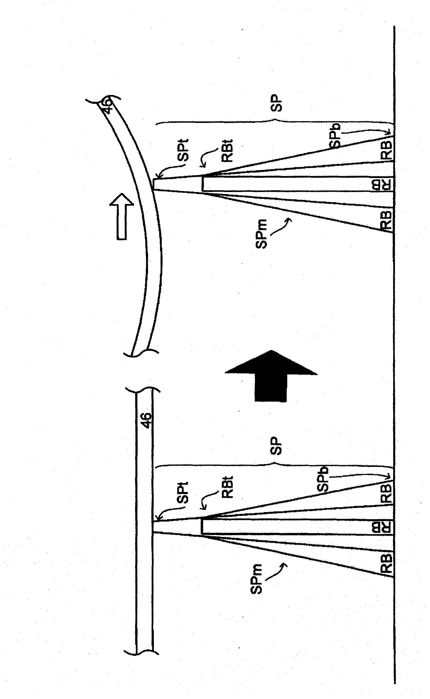
[0003] However, in such a backlight unit 149, the deformation of the resin diffuser plate 146 and the like due to the heat of the fluorescent tubes 142, in particular, is transmitted according to the ON / OFF of the fluorescent tubes 142. The deformation of the diffuser plate 146 etc. due to the influence of heat or heat dissipation becomes a problem

Method used


Image

  • Support unit, lighting device, and display device
  • Support unit, lighting device, and display device
  • Support unit, lighting device, and display device

Examples


Embodiment approach 1

[0029] One embodiment will be described below with reference to the drawings. In addition, for convenience of explanation, the reference numerals of components and the like may be omitted, and in such a case, refer to other drawings.

[0030] Figure 4 It is an exploded perspective view of a liquid crystal display device 89 as an example of a display device. As shown in the figure, the liquid crystal display device 89 includes a liquid crystal display panel 39 , a backlight unit (illumination device) 49 , and a bezel 59 .

[0031] The liquid crystal display panel 39 is constituted by bonding an active matrix substrate 32 including switching elements such as TFTs (Thin Film Transistor: Thin Film Transistor) and a counter substrate 33 facing the active matrix substrate 32 with a sealing member (not shown). combine. Further, liquid crystal (not shown) is injected into the gap between the two substrates 32 and 33 (polarizing films 34 and 34 are mounted so as to sandwich the act...


PUM


Abstract

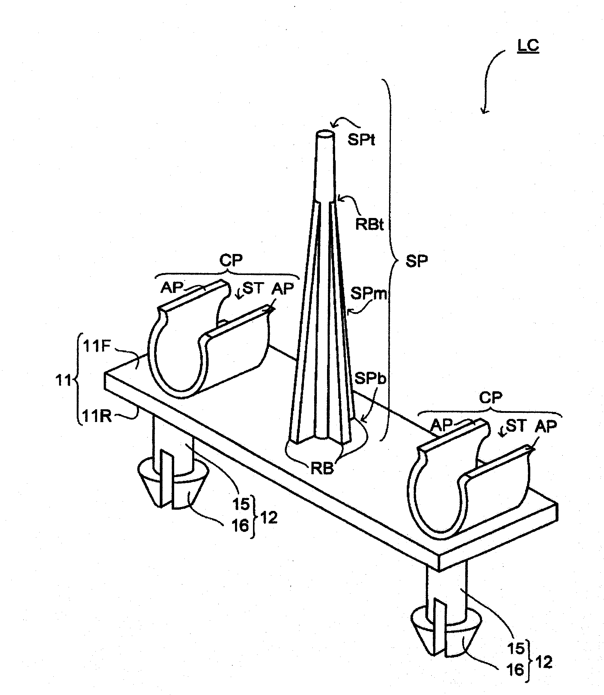
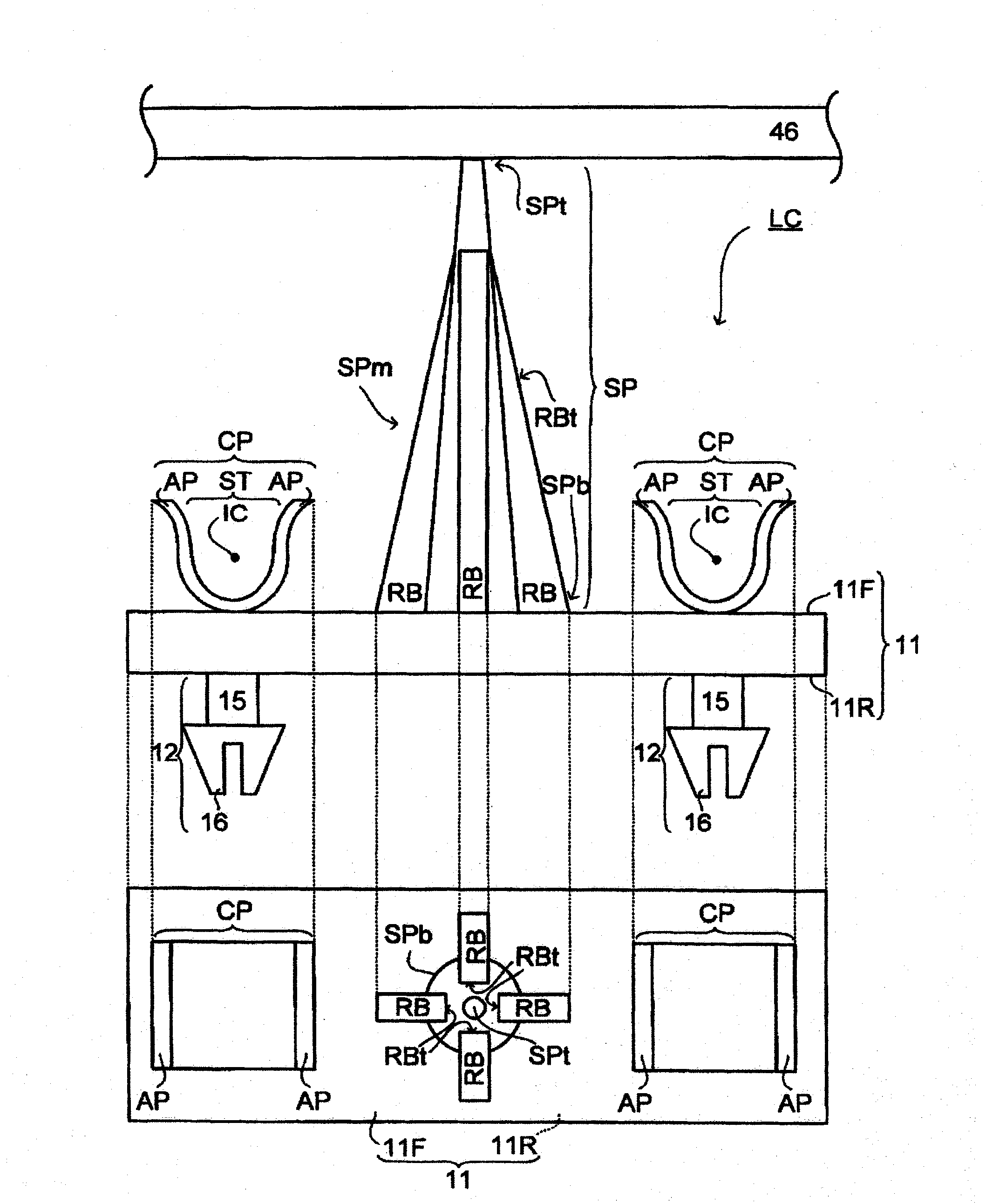
The invention provides a support unit, a lighting device and a display device. A lamp clip (LC) includes a support pin (SP) making contact with and supporting an optical sheet such as a diffusion plate (46), and also includes ribs (RB) rising from the outer periphery of the support pin (SP) and reinforcing the support pin (SP).

Description

technical field [0001] The present invention relates to a supporting unit for supporting an optical sheet, and further relates to a display device such as a lighting device including the supporting unit and a liquid crystal display device equipped with the lighting device. Background technique [0002] Conventionally, a diffusion plate (optical sheet) for diffusing light from a light source is mounted on a backlight unit of a liquid crystal display device, and a lens sheet (optical sheet) for improving light-gathering performance is further mounted on the diffusion plate. And, if Figure 5 As shown, these diffuser plates 146 and lens sheets 147 are supported by support pins sp of the lamp clip 1c attached to the bottom surface 144B of the backlight chassis 144 (see Patent Document 1). [0003] However, in such a backlight unit 149, the deformation of the resin diffuser plate 146 and the like due to the heat of the fluorescent tubes 142, in particular, is transmitted accordin...

Claims


Application Information

Patent Timeline
IPC IPC(8): F21V17/00F21S2/00G02F1/1333G02F1/13357F21Y103/00
CPCF21V19/009G02F2201/465G02F1/133608G02F1/133603G02F1/133604
Inventor 长谷川洋一
Owner SHARP KK
Learn More