

Arc-starting method for multi-electrode single-side welding device and multi-electrode single-side welding device
A single-sided welding, multi-electrode technology, applied in welding equipment, arc welding equipment, manufacturing tools, etc., can solve the problems of longer lead plates, time required, and increased use of auxiliary agents, etc., to achieve reliable arc generation and low usage. Reduced and excellent work efficiency
- Summary
- Abstract
- Description
- Claims
- Application Information
AI Technical Summary
Problems solved by technology
Method used
Image

Examples
Embodiment Construction
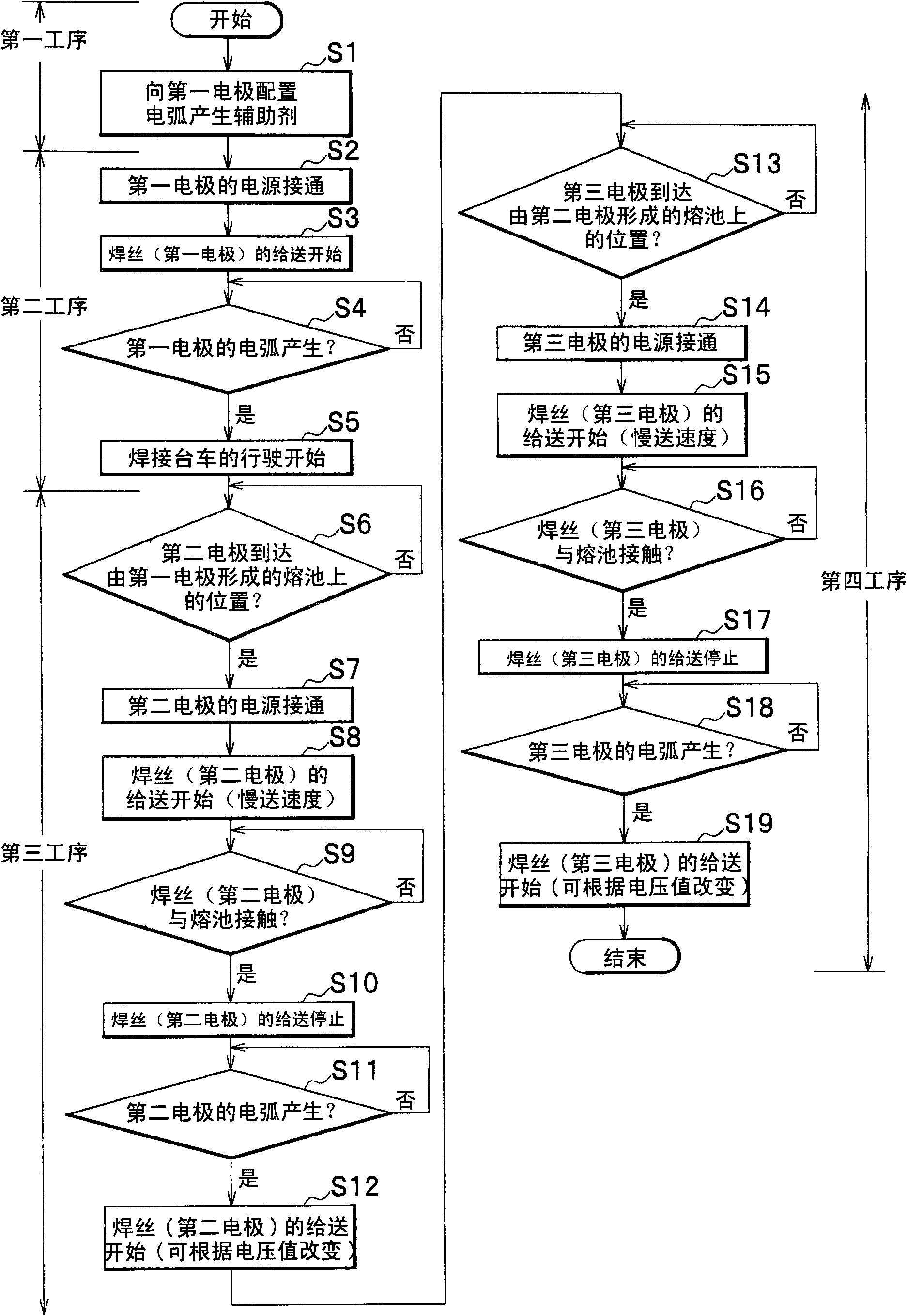
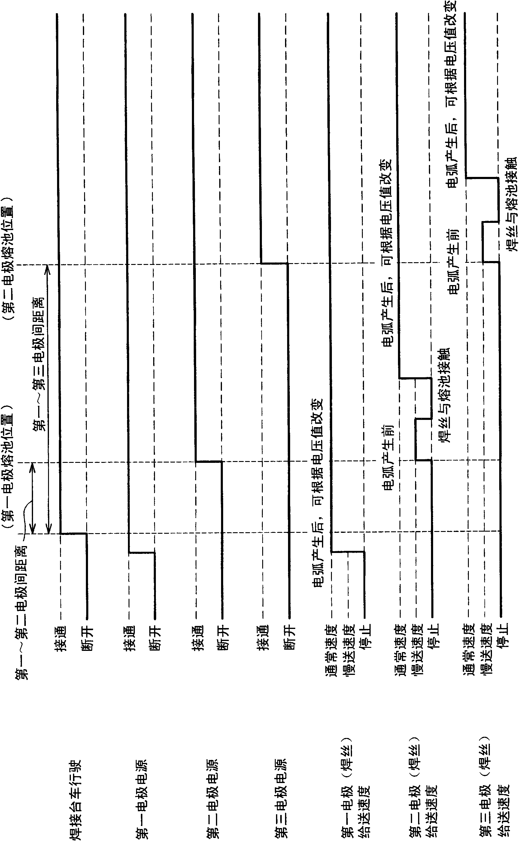
[0021] The arc starting method of the multi-electrode single-side welding device according to the present invention and the multi-electrode single-side welding device which starts arc welding by the arc starting method will be described with reference to the drawings.
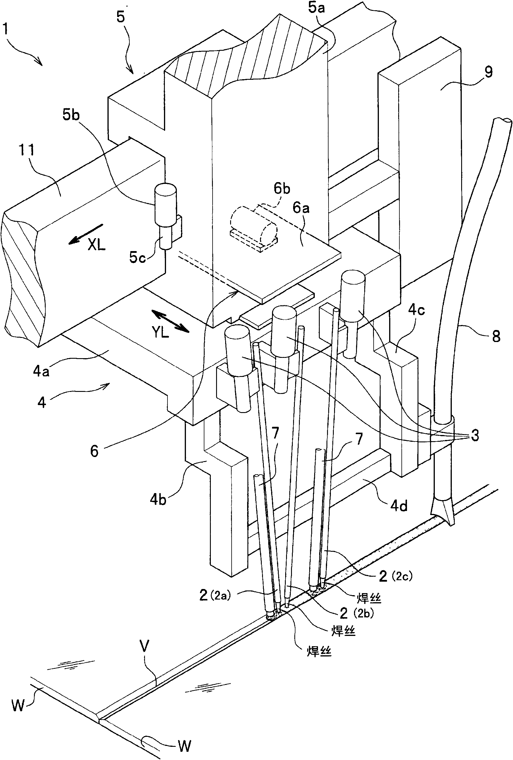
[0022] First, refer to image 3 , Figure 4 , to illustrate the multi-electrode single-sided welding device. and, if necessary, refer to the figure 2 .
[0023] Such as image 3 As shown, a multi-electrode single-sided welding device (hereinafter, sometimes referred to as a welding device) 1 is welded by pairs of electrodes 2 (first electrode 2a, second electrode 2b, and third electrode 2c) mounted on a welding trolley 4. The material W is arc welded, and the electrode 2 is the fed wire. In addition, during welding, the control unit 9 controls the vehicle moving mechanism 5 to move the welding trolley 4 along the welding line (groove line) V of the butted material W to be welded, and the control unit 9 co...
PUM
 Abstract
Description
Claims
Application Information