Method and device of wirelessly outputting thermoelectric force signal for multi-point temperature measuring of rotator

A thermoelectric potential signal, multi-point temperature technology, applied in the direction of auxiliary devices, measuring/indicating equipment, turning equipment, etc., can solve the problems of complex structure, difficulty in fidelity of thermoelectric signal output, and affecting measurement accuracy, so as to achieve simple device and avoid The effect of high-speed rotating centrifugal force

Inactive Publication Date: 2011-08-24
SOUTH CHINA UNIV OF TECH
View PDF4 Cites 7 Cited by
  • Summary
  • Abstract
  • Description
  • Claims
  • Application Information

AI Technical Summary

Problems solved by technology

The disadvantages of these methods are: (1) a thermoelectric potential signal will be collected at both ends of a standard thermocouple, and a set of signal lead-out devices are required for each output of a thermoelectric potential signal. If the temperature of n points is measured simultaneously with a thermocouple, it will be necessary The structure of 2n sets of devices is bound to be very complicated; (2) In the rotating state, the friction between the dynamic and static body of the signal transmission conductor will generate additional thermoelectric potential, that is, the output fidelity of the thermoelectric signal is difficult, which affects the measurement accuracy
At present, only the natural thermocouple composed of the tool and the workpiece leads to the signal at one end of the mercury current collector, thimble, and brush, and the other end is on the non-rotating body. No one has yet studied the problem of deriving the signal of the standard thermocouple of the rotating body. , since both ends are on the rotating body, and the ends must be insulated from each other

Method used


Image

  • Method and device of wirelessly outputting thermoelectric force signal for multi-point temperature measuring of rotator
  • Method and device of wirelessly outputting thermoelectric force signal for multi-point temperature measuring of rotator
  • Method and device of wirelessly outputting thermoelectric force signal for multi-point temperature measuring of rotator

Examples


Embodiment Construction

[0020] The present invention will be described in further detail below in conjunction with the accompanying drawings, but the scope of protection claimed by the present invention is not limited to the scope described in the embodiments.

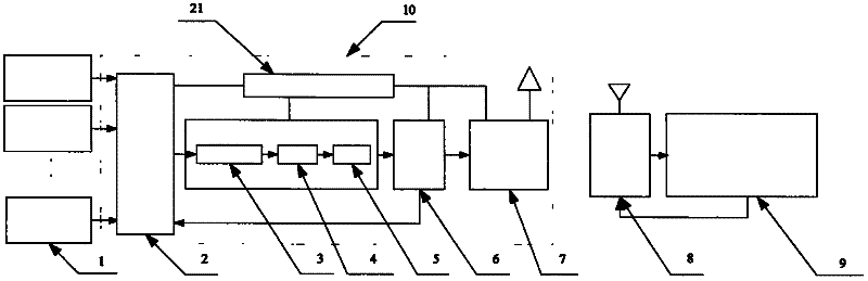
[0021] Such as figure 1 As shown, a wireless output device for measuring thermoelectric potential signals at multiple points on a rotating body includes a K-type thermocouple 1, a thermoelectric potential signal acquisition and transmission module 10, a wireless receiving module 8 and a PC 9; a thermoelectric potential signal acquisition and transmission module 10 includes multi-channel electronic switch 2, amplifier circuit 3, filter circuit 4, A / D conversion circuit 5, CPU6, wireless transmitting module 7 and battery 21, multi-channel electronic switch 2, amplifier circuit 3, filter circuit 4, A / D The conversion circuit 5 and the CPU6 are sequentially connected by signals, and the CPU6 is also respectively connected with the multi-channel e...


PUM


Abstract

The invention discloses a method and a device of wirelessly outputting thermoelectric force signals for multi-point temperature measuring of a rotator. The device comprises K type thermocouples, a thermoelectric force signal acquisition and emission module, a wireless reception module and a PC, wherein the wireless reception module is connected with the PC via a wire; a plurality of K type thermocouples are respectively arranged on a rotator, the temperature of which is to be measured; the K type thermocouples are connected with multipath electronic switches via wires; the thermoelectric force signal acquisition and emission module is fixed in the center of the rotator tail or sleeved on the rotator, so that the center of gravity of the thermoelectric force signal acquisition and emission module is concentric with a rotation axis of the rotator. The PC of the invention arranges serially acquired signals into thermoelectric force signal sequence of different paths at different time points according to the number of paths, and realizes real time acquisition, output and display of multi-point temperature of the rotator, well solving the leading out problem of multiple singles under rotation state and avoiding the generation of additional thermoelectric force.

Description

technical field [0001] The invention relates to a temperature measurement of a machined component, in particular to a multi-point temperature measuring device and method of a rotating body for wireless transmission of thermoelectric potential signals, which are used for measuring the temperature of the rotating body. Background technique [0002] In the operation of mechanical equipment, many parts are rotating bodies, and in some cases it is necessary to measure the temperature of several points of these rotating bodies. For example, in the study of mechanical cutting mechanism, it is necessary to measure the temperature of turning rotating workpiece or milling rotating tool. At present, only the natural thermocouple composed of tool-workpiece uses current collectors, thimbles, and brushes to lead out one end of the signal, and the other end is on a non-rotating body. These methods are based on electrical conductors that lead the thermoelectric potential signal of the rotat...

Claims


Application Information

Patent Timeline
Patent Type & Authority Applications(China)
IPC IPC(8): B23Q17/00B23Q17/09B23B25/00B23C9/00
Inventor 全燕鸣刘志军刘汉瑞
Owner SOUTH CHINA UNIV OF TECH
Why Eureka
Try Eureka