In-situ soil body layered settlement monitoring device and method

A layered settlement and settlement monitoring technology, applied in the field of foundation soil survey, construction, infrastructure engineering, etc., can solve the problems of troublesome data collection, accelerated soil settlement, and heavy workload of technicians.

Active Publication Date: 2019-08-27
CHINA JK INST OF ENG INVESTIGATION & DESIGN +1
View PDF3 Cites 6 Cited by
  • Summary
  • Abstract
  • Description
  • Claims
  • Application Information

AI Technical Summary

Problems solved by technology

At present, the layered settlement of in-situ soil is mainly observed by embedding layered markers inside the in-situ soil. This method is to bury the layered markers in an in-situ soil layer according to the actual needs of the project, and measure the soil settlement below it. Among them, the bottom of the mark is buried in the soil layer of the measured depth, and the settlement change of the measured soil layer is led to the ground through the benchmark pole to be measured by the method of leveling elevation measurement. There are three problems in the actual implementation of this method: (1) On-site analysis There are multiple layers of subsidence markers, and each subsidence marker is buried in different boreholes. There is often a large distance between the boreholes. It reflects the continuous layered settlement data in the vertical direction of a certain monitoring point; (2) After the settlement mark is buried, the backfilled borehole becomes a channel for water infiltration. The law of settlement under the condition of natural infiltration of in-situ soil; (3) The scattered embedding of settlement targets also brings troubles to data collection, and the workload of technicians is relatively large

Method used


Image

  • In-situ soil body layered settlement monitoring device and method
  • In-situ soil body layered settlement monitoring device and method
  • In-situ soil body layered settlement monitoring device and method

Examples


Embodiment Construction

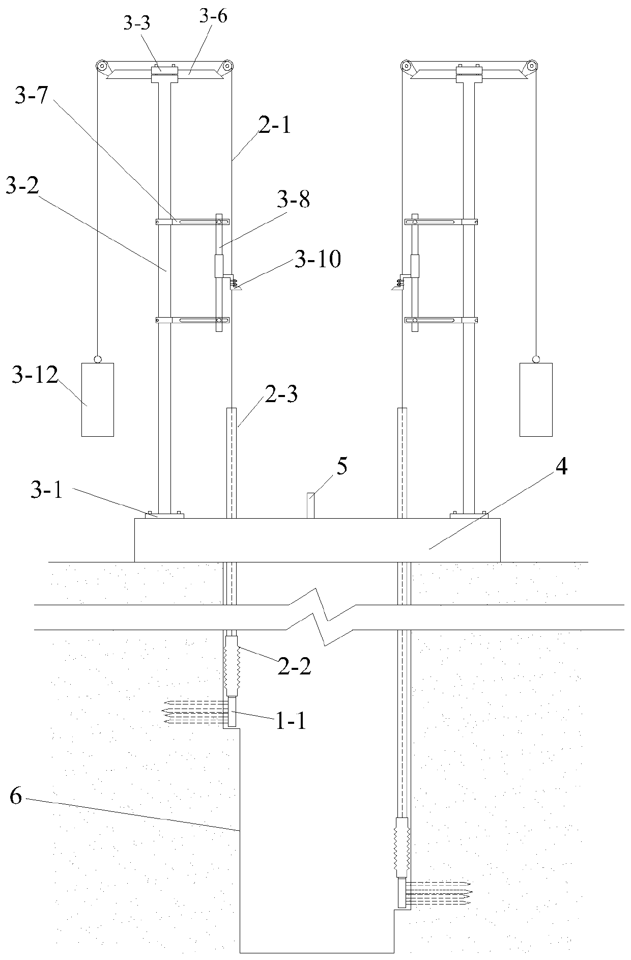
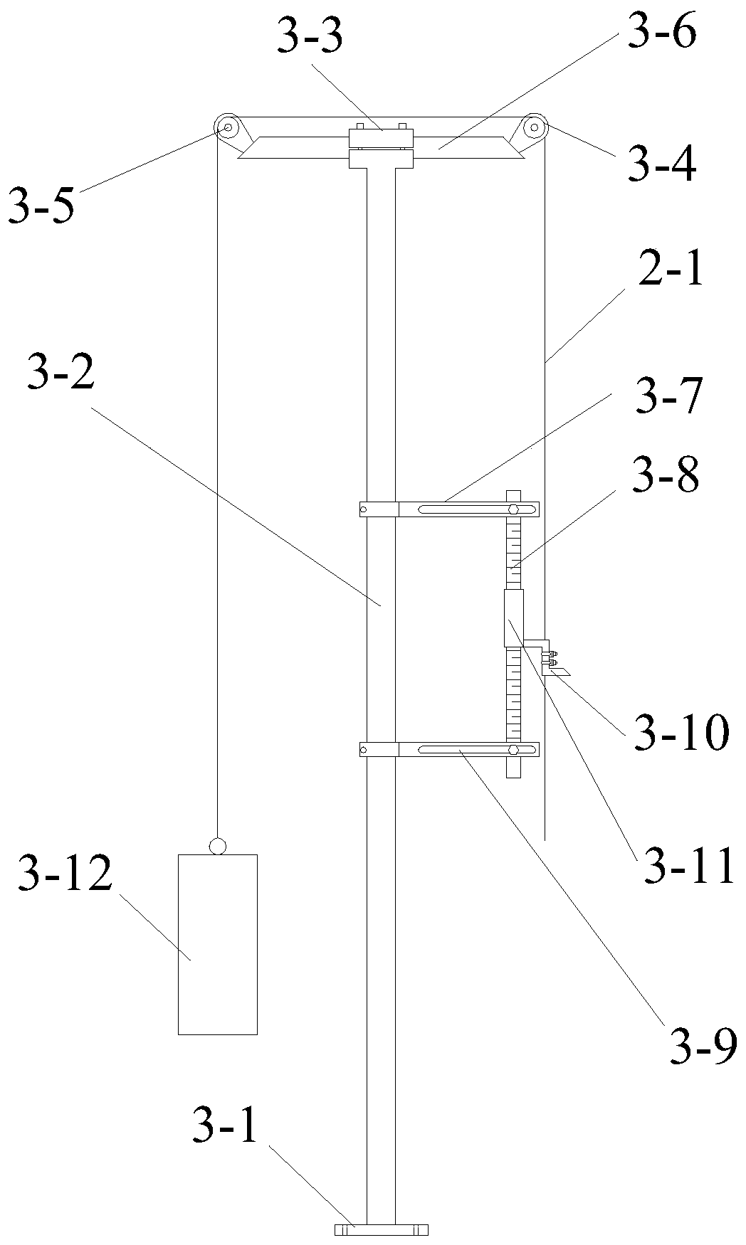
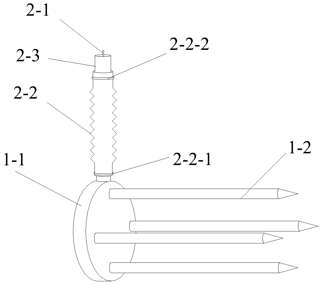
[0088] Such as figure 1 , figure 2 , image 3 with Figure 4 The shown in-situ soil layered settlement monitoring device includes a circular base 4 arranged on the top of the exploratory well 6 and a plurality of circular bases evenly arranged along the circumferential direction of the circular base 4 to monitor the settlement of the in-situ soil at different depths. The settlement monitoring device for monitoring, the top of the exploratory well 6 is flush with the in-situ soil surface, a plurality of the settlement monitoring devices are the same, and each of the settlement monitoring devices includes a The anchor mechanism, the settlement transmission mechanism connected with the anchor mechanism and the settlement measurement mechanism connected with the settlement transmission mechanism, the anchor mechanism includes a circular base 1-1 and a plurality of circular bases 1-1-1 side and is used to insert steel nails 1-2 into the in-situ soil body. The settlement transmi...


PUM


Abstract

The invention discloses an in-situ soil body layered settlement monitoring device and method. The device comprises a circular base arranged on the top of an exploratory well and multiple settlement monitoring devices. Each settlement monitoring device comprises an anchoring mechanism, a settlement transmission mechanism and a settlement measuring mechanism, wherein the anchoring mechanism comprises a circular base and multiple steel nails, the settlement transmission mechanism comprises a measuring rope, a telescopic pipe and a protection pipe, and the settlement measuring mechanism comprisesa stand column, a pulley mechanism, a measuring scale and a balance weight. The method includes the following steps that firstly, the settlement measuring monitoring devices are installed; secondly, backfill consolidation is conducted; thirdly, the settlement measuring mechanisms are fixed and adjusted; and fourthly, layered settlement monitoring and data treatment are conducted. By means of the in-situ soil body layered settlement monitoring device and method, design is reasonable, the cost is low, time and labor are saved, installation is convenient, soil body deformation monitoring at different heights of an in-situ soil body is achieved, and practicability is high.

Description

technical field [0001] The invention belongs to the technical field of geotechnical engineering testing, and in particular relates to an in-situ soil layer settlement monitoring device and method. Background technique [0002] Layered settlement monitoring of rock and soil foundation is an important content of geotechnical engineering monitoring. It is often used to judge whether the engineering characteristics of each soil layer meet the design requirements, as an important basis for controlling the construction progress, judging the stable state of the foundation, and evaluating the effect of foundation treatment. At present, the layered settlement of in-situ soil is mainly observed by embedding layered markers inside the in-situ soil. This method is to bury the layered markers in an in-situ soil layer according to the actual needs of the project, and measure the soil settlement below it. Among them, the bottom of the mark is buried in the soil layer of the measured depth...

Claims


Application Information

Patent Timeline
Patent Type & Authority Applications(China)
IPC IPC(8): E02D1/00
CPCE02D1/00
Inventor 刘争宏于永堂张龙郑建国王俊茂陈冉升曹杰刘智王云南乔建伟周远强
Owner CHINA JK INST OF ENG INVESTIGATION & DESIGN
Why Eureka
Try Eureka