Implant light emitting device high brightness fluorescent lamp

A light-emitting device and fluorescent technology, which is applied to discharge lamps, gas discharge lamps, and parts of gas discharge lamps, etc., can solve the problems of not being able to achieve the maximum brightness efficiency of fluorescent powder, affecting the brightness of lamps, and not being reasonably fully utilized in space. , to achieve the effect of colorful life, easy production and processing, and cost reduction

Inactive Publication Date: 2011-08-24
翟长鸿
View PDF8 Cites 1 Cited by
  • Summary
  • Abstract
  • Description
  • Claims
  • Application Information

AI Technical Summary

Problems solved by technology

Its opaque characteristics determine that the brightness inside the lamp tube is higher than the brightness outside the lamp tube. The thicker the phosphor coating is, the lower the brightness outside is. If the powder coating is too thin, there will be no brightness at all, and it cannot control the production process
[0006] Therefore, the thickness of the phosphor will not only affect the brightness of the lamp, but also affect the cost, quality and standard of the product
And they can't reach the theoretical maximum brightness performance of phosphor powder anyway, and the baking process will also reduce the maximum brightness of fluorescent materials, so that the electro-optical conversion efficiency of previous fluorescent lamps has not reached the theoretical maximum value.
[0007] Moreover, the space inside the tube has not been reasonably fully utilized.

Method used


Image

  • Implant light emitting device high brightness fluorescent lamp
  • Implant light emitting device high brightness fluorescent lamp
  • Implant light emitting device high brightness fluorescent lamp

Examples


specific Embodiment approach

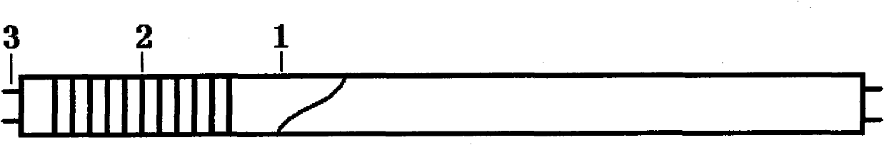
[0064] Specific implementation methods: such as figure 1 , 1 is a transparent shell, 2 is a fluorescent built-in, and 3 is an electrode. Its fluorescent built-in can be figure 1 , 2 , 3, 4, 5, 6, 7, 8, 9, 10, 11, etc. in any shape or combination; it can also be any figure other than them. You can use fluorescent paper or cloth or plastic or glass to make it into the desired shape or figure and put it into the lamp tube to fix it. You can also apply fluorescent substances on the paper, plastic or glass. Put it into the lamp tube and fix it.

[0065] It is also possible to coat the specimens of flowers, birds, fish and insects with fluorescent substances, then put them into tubes and fix them. All kinds of figure carvings can be directly loaded into the lamp and sparkle, lifelike.

[0066] It can be made into standard lamps of national standard, and can also be made into non-national standard decorative and artistic lamps according to enterprise standards. The market is h...


PUM


Abstract

The invention relate to an implant light emitting device high brightness fluorescent lamp in the field of illumination. The traditional light emitting device fluorescent lamp has low brightness as a method of coating a fluorescent material on an inner wall of a tube is adopted. The fluorescent lamp provided by the invention is characterized in that fluorescent implants are arranged in a transparent shell in a maximizing way, and the ratio of the area of the fluorescent implant to the area of the shell is 0.01-100. The fluorescent light emitted by the implant can release the brightness of light to the greatest extent by virtue of a completely transparent glass bulb. The light-emitting area is dozens of times of the original light-emitting area; meanwhile, a shape structure is utilized to form corner reflection auto-excitation, thus the brightness can reach a theoretical maximum; the implant can adopt fluorescent paper, the fluorescent paper has the patterns of flowers, birds, fishes and insects, or animals, or plants, or characters, or head portraits, or graphics or a calligraphy and painting or any combination thereof, and the fluorescent paper is placed in a transparent shell to directly emit light; energy is saved, and consumption is reduced; and the fluorescent lamp is universal in the traditional lantern and can be directly made into an industrial art lantern or a large-scale electronic luminescent screen.

Description

technical field [0001] The invention relates to a high-brightness fluorescent lamp of a light-emitting device in the field of illumination. Background technique [0002] The fluorescent lamps used in the past light-emitting devices are all coated with fluorescent substances on the inner wall of the glass tube of the shell, and the ultraviolet rays in the tube directly irradiate the fluorescent powder on the inner wall of the tube to emit light, but the fluorescent substance itself is opaque. It emits light under the excitation of ultraviolet rays, but when the fluorescent lamp emits light, the brightness of the inside and outside of the lamp tube is different. [0003] The brightness of the fluorescent powder on the inside of the lamp tube that is directly exposed to ultraviolet rays is the highest, so the brightest light is inside the tube! And we can't see it from the outside of the tube. The light we see on the outside of the tube: it's just the brightest light on the i...

Claims


Application Information

Patent Timeline
Patent Type & Authority Applications(China)
IPC IPC(8): H01J61/00H01J61/35H01J61/30
Inventor 翟长鸿
Owner 翟长鸿
Why Eureka
Try Eureka