
On-chip integration paster antenna

A technology that integrates patches and antennas, applied in resonant antennas, antenna supports/mounting devices, and structural forms of radiation elements, can solve problems such as complex processes, influence of silicon materials, high loss, etc., and achieve simple manufacturing process and low cost , the effect of small loss

Active Publication Date: 2014-03-05
TSINGHUA UNIV
View PDF3 Cites 0 Cited by
  • Summary
  • Abstract
  • Description
  • Claims
  • Application Information

AI Technical Summary

Problems solved by technology

[0004] However, there are still many problems with the integration of on-chip antennas using standard CMOS manufacturing processes, the most important of which is the influence of silicon materials.
On the one hand, compared with air (ε r ≈1) has a high dielectric constant (ε r =11.9), the silicon base will confine most of the radiated energy in the material instead of radiating it into space, resulting in low overall radiation efficiency of the antenna
On the other hand, the resistivity of silicon wafers commonly used in the industry is only about 10Ω·cm, showing high loss characteristics, which further deteriorates the radiation performance
Therefore, due to the influence of the high-loss silicon base in the general antenna structure, the radiation performance achieved is not ideal, and the absolute gain is less than 0dBi
At the same time, although the radiation performance can be improved by improving the resistivity of the silicon base by proton implantation, adding dielectric lenses, and completing the micromachining of the silicon base by deep reactive ion etching DRIE, the relatively complicated process will greatly increase the manufacturing cost, and it is different from the existing The standard CMOS process is not compatible with

Method used


Image

  • On-chip integration paster antenna
  • On-chip integration paster antenna
  • On-chip integration paster antenna

Examples


Embodiment Construction

[0027] In order to make the above objects, features and advantages of the present invention more comprehensible, the present invention will be further described in detail below in conjunction with the accompanying drawings and specific embodiments.

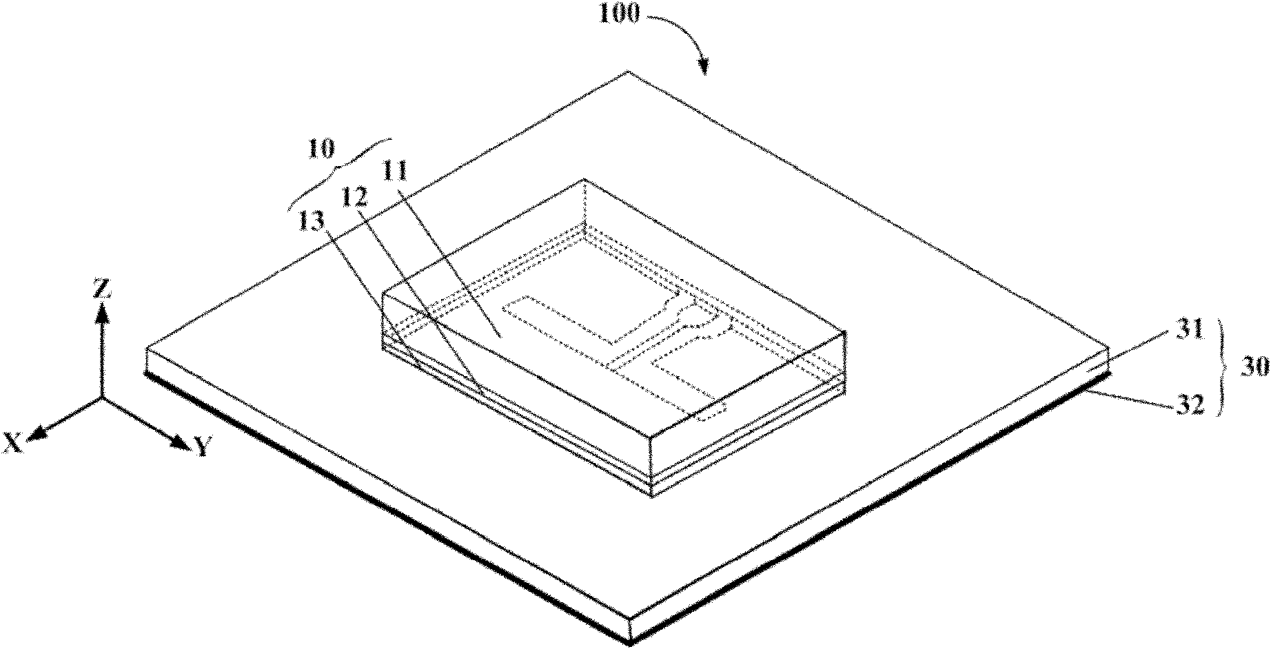
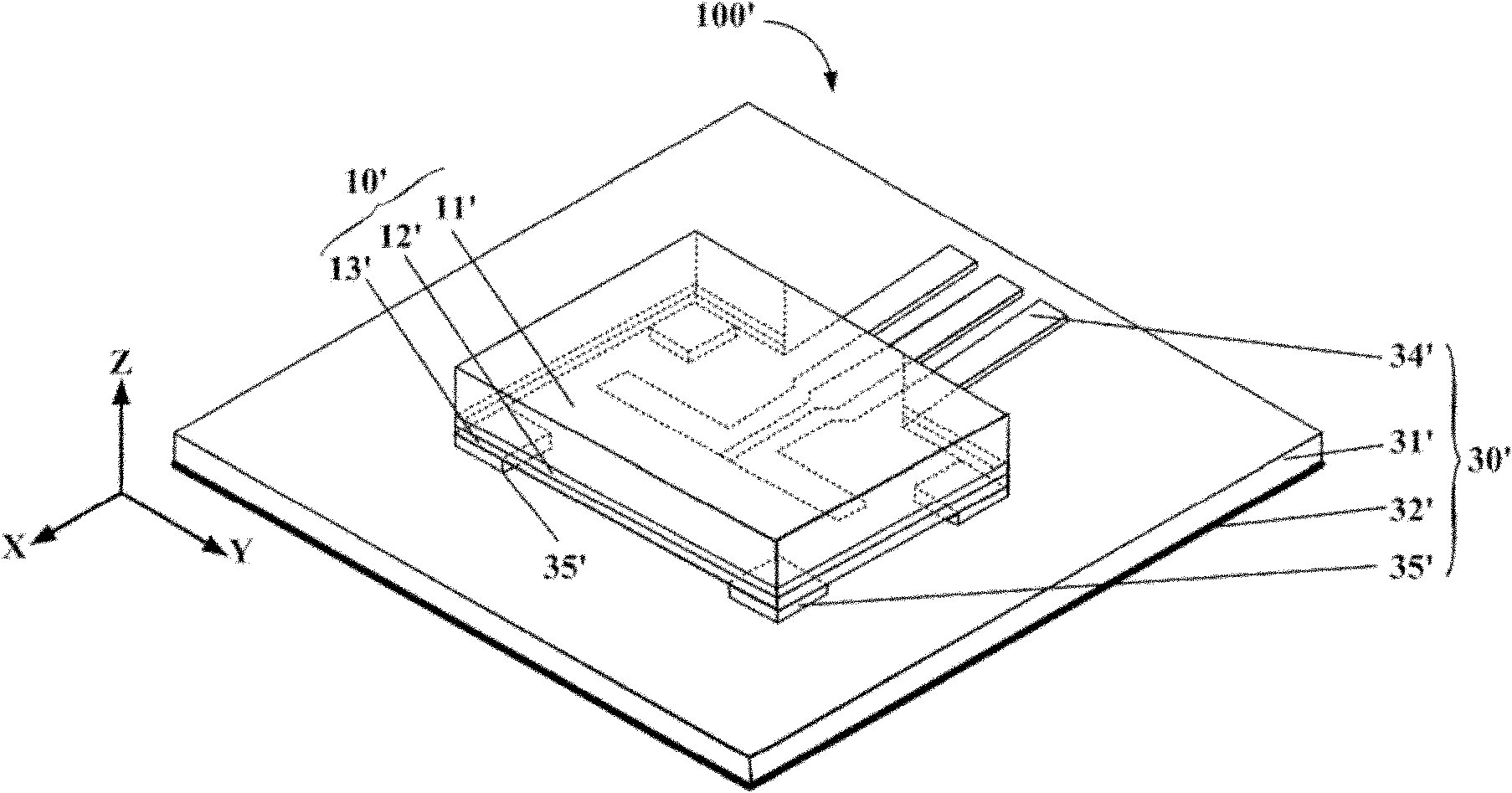
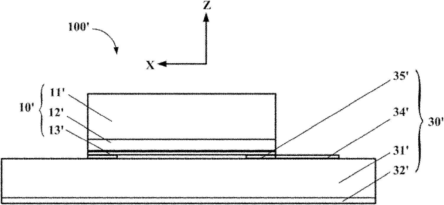
[0028] refer to figure 1 and figure 2 , shows that an on-chip integrated patch antenna 100 of the present invention includes an on-chip device 10 and an off-chip device 30 , and the on-chip device 10 is placed on the off-chip device 30 upside down.

[0029] The device-on-chip 10 includes a silicon chip 11 , an isolation layer 12 and a metal patch unit 13 .

[0030] Wherein, the silicon wafer 11 is a low-resistance silicon wafer, and its dielectric constant and resistivity can be selected according to actual needs. In this embodiment, the dielectric constant of the silicon wafer 11 is 11.9, and the resistivity is 10Ω·cm. Its thickness can also be selected according to the actual situation. In general, in order to reduce the imp...


PUM


Abstract

The invention provides an on-chip integration paster antenna which comprises an on-chip device and an outer-chip device connected with the on-chip device, wherein the on-chip device comprises mutually fitted silicon wafers, an isolating layer and a metal paster unit, and the isolating layer is located between the silicon wafers and the metal paster unit; the outer-chip device comprises a dielectric layer and a metal land; the metal paster unit is connected with the dielectric layer; and the dielectric layer is located between the metal paster and the metal land. By using the on-chip integration paster antenna, the radiance of the antenna can be improved; and the manufacturing process is simple, and the cost is low.

Description

technical field [0001] The invention relates to the technical field of wireless communication, in particular to an on-chip integrated patch antenna. Background technique [0002] Wireless communication has developed rapidly in recent years. With the increasing demand for low-cost, broadband, high-speed and small wireless devices, especially for millimeter-wave band devices, System-on-Chip (SoC) has become an important solution to address the above requirements. The existing system-on-chip (SoC) and system-in-package (SIP) technology can already integrate all parts of the receiver's RF front-end, intermediate frequency, and digital baseband circuits into a tiny package. In order to realize a complete system on chip, integrated antenna technology on chip becomes the main problem we need to study. [0003] In the millimeter wave frequency band, 60GHz is very attractive. For high-speed Internet, data communication, especially wireless personal area network (WPAN) applications...

Claims


Application Information

Patent Timeline
Patent Type & Authority Patents(China)
IPC IPC(8): H01Q9/04H01Q1/38H01Q1/22
Inventor 高扬张志军陈文华冯正和
Owner TSINGHUA UNIV
Learn More