Packaging sensors for long term implant

Inactive Publication Date: 2008-03-25
PACESETTER INC
13 Cites 50 Cited by

AI-Extracted Technical Summary

Problems solved by technology

However, no concern is expressed in the disclosur...

Benefits of technology

[0010]As noted earlier, smart packaging is a very important part of making an implantable device. The device housing has to be sufficiently robust, both mechanically and chemically, to provide adequate protection from the human body. Indeed, packaging the pressure sensor, retaining its integrity and sensitivity, and protecting the device have long been a pursuit for those in the industry. The present invention proposes a robust and hermetic seal packaging technique for an implantable sensor without endangering device integrity and is a three step effort.
[0011]The packaging of the pressure sensor is performed with two key objectives in mind: sensor integrity and hermetic sealing of the device. The sensor is packaged in three stages. The first step is to seal the electrical conductors of the sensor in an insulating substance such as ceramic or glass. Then, as a possible second step, a very thin film (on the order of microns in thickness) of insulating material such as parylene is coated over the device as an internal layer. This is proposed, but not absolutely necessary, to prevent any contact between the device components and the ...

Abstract

According to this technique of packaging a sensor device implantable in a living body so as to provide protection of the sensor device and to the living body itself, an electrical conductor of the sensor device is sealed in an insulating substrate extending between proximal and distal ends. The distal end of the electrical conductor is externally connected to an external sensor on the sensor device and the proximal end of the electrical conductor is externally connected to a distal end of a lead wire extending proximally to a pulse generator and these connections are embedded in an insulative sheath. The external sensor, substrate, and insulative sheath are encapsulated in a thin film of hermetic material without interference with the lead wire. In another embodiment, a layer of insulating material may underlie the hermetic material to encapsulate the external sensor and the substrate.

Application Domain

Technology Topic

Image

  • Packaging sensors for long term implant
  • Packaging sensors for long term implant
  • Packaging sensors for long term implant

Examples

  • Experimental program(1)

Example

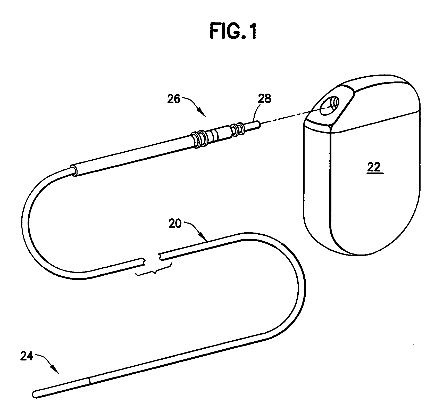
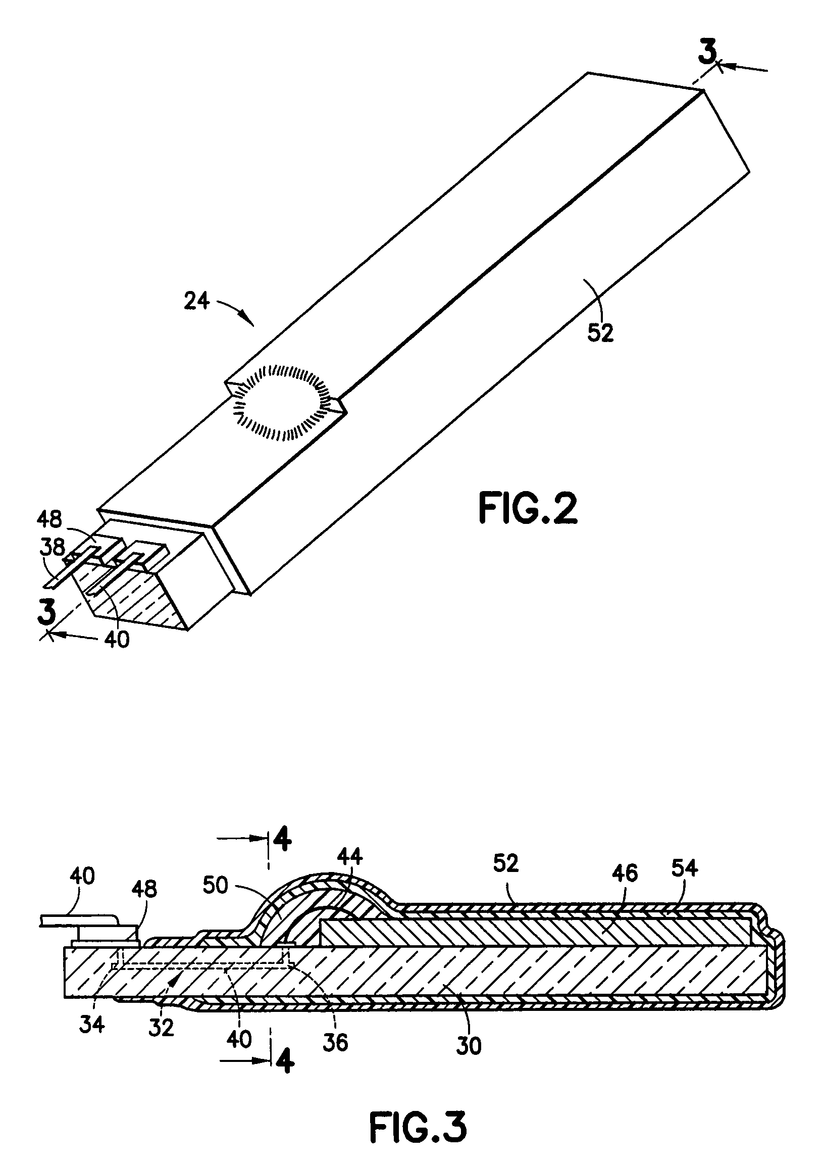
[0022]Refer now to the drawings and, initially, to FIG. 1 in which is shown an implantable lead 20 used in combination with an implantable stimulation device or pulse generator 22 such as a pacemaker or defibrillator and interconnects a sensor device 24 intended to be introduced into a living body, for example, into an organ such as the heart, and an electrical connector 26 at a proximal end 28 for attachment to the stimulation device. Although the present invention will be described with reference to the embodiments shown in the drawings, it should be understood that the present invention can be embodied in many alternate forms or embodiments. For example, the sensor device 24 may be located inside the lead 20 at various other locations than the one illustrated. Also, a number of sensor devices 24 could be incorporated into the lead 20. In addition, any suitable size, shape or type of elements or materials could be used.
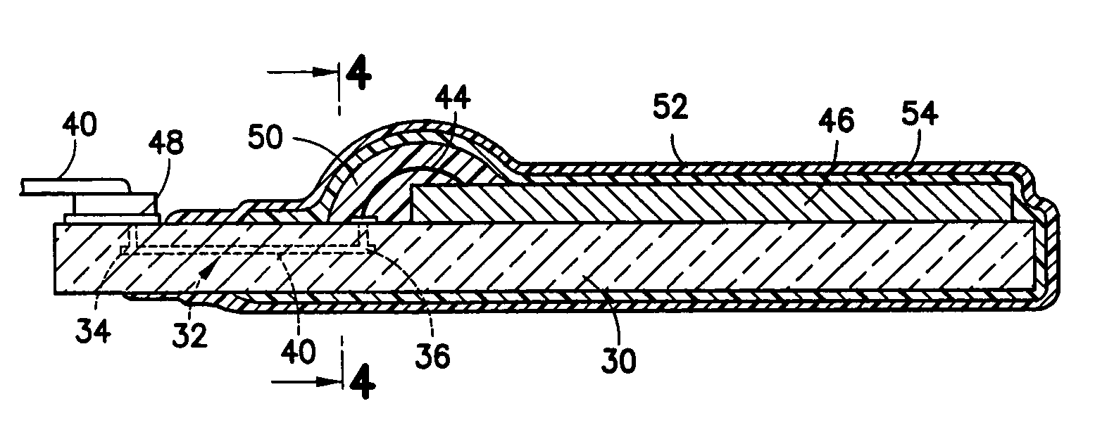
[0023]For a more detailed description of the invention, turn now to FIGS. 2, 3, and 4. The sensor device 24 is packaged so as to provide protection of the sensor device itself in the environment of the living body and also to provide protection to the living body from the sensor device. To this end, the packaged sensor device 24 includes an insulating substrate 30 with a feedthrough region 32 extending between proximal and distal ends 34, 36, respectively, of the substrate. The substrate 30 may be composed, for example, of ceramic material or glass. Electrical conductors 38 and 40 extending from the electrical connector 26 are received in the feedthrough region 32 and extend between the proximal and distal ends of the feedthrough region.
[0024]Bond wires 42, 44 connect, respectively, the distal ends of the electrical conductors 38, 40 to an external sensor 46 on the substrate 30 and the electrical conductors may be attached to the substrate 30 by means of a conductive pad 48 such as a Kovar pad for introduction to the feedthrough region 32. The sensor 46 may be a temperature sensor or a pressure sensor or it may be, for example, an integrated pressure and temperature sensor chip, a catheter chip manufactured by Fraunhofer Institut für Mikroelektronische Schaltungen und Systeme of Duisburg, Germany being suitable for purposes of the invention. It will be apparent to those skilled in the art that sensor 46 may be any suitable sensor, for example, electrical sensors, transducers, and the like.
[0025]An insulative deposit of protective material 50 composed, for example, of epoxy is applied to fully embed the bond wires 42, 44 to electrically insulate them from each other and from all other electrically conductive components which may be in the vicinity of the sensor device 24. Finally, at least the external sensor 46 and the substrate 30, and part of the insulative deposit of protective material 50, are encapsulated in a thin film 52 of hermetic material, for example, gold, titanium, platinum or carbon based materials such as amorphous carbon, diamond like carbon and diamond. However, it is important that the thin film 52, preferably with a thickness in the range of about 10 nm to 0.1 mm, must be applied so as not to interfere with the conductivity of the lead 20.
[0026]While not necessary for the performance of the invention, it is desirable to encapsulate at least the external sensor 46 and the substrate 30 in a layer of insulating material 54 which may be composed of parylene or other suitable insulating or non-conductive material. In one embodiment, insulating material 54 has a thickness in the range of about 5.0 nm to 0.5 mm. As with the thin film 52, the insulating material 54 must be applied so as not to interfere with the conductivity of the lead 20.
[0027]It should be understood that the foregoing description is only illustrative of the invention. Various alternatives and modifications can be devised by those skilled in the art without departing from the invention. Accordingly, the present invention is intended to embrace all such alternatives, modifications and variances which fall within the scope of the appended claims.

PUM

no PUM

Description & Claims & Application Information

We can also present the details of the Description, Claims and Application information to help users get a comprehensive understanding of the technical details of the patent, such as background art, summary of invention, brief description of drawings, description of embodiments, and other original content. On the other hand, users can also determine the specific scope of protection of the technology through the list of claims; as well as understand the changes in the life cycle of the technology with the presentation of the patent timeline. Login to view more.

Similar technology patents

Method and apparatus for increasing angiogenic, growth factor in heart muscle

InactiveUS7107997B1Exposure be continuousAvoid damageDiagnosticsSurgical instrument detailsAngiogenesis FactorFactor ii
Owner:MOSES JEFFREY WARREN +3

Classification and recommendation of technical efficacy words

Why Eureka
Try Eureka